3 keypad insert descriptions, Keypad insert descriptions – Daktronics OmniSport 2000 Timing Console User Manual
Page 168

150
Pace Clock Mode Operation, Menus & Settings
Step Type
Lane details
are contained
in the right
LCD. For
example, the
lane and step
numbers
currently
shown are
identified on
the top row.
(bottom row word on right screen [ex. PACE]) Following is a list of possible steps:
Beg Circuit
–– for a workout, enter a combination of desired steps: swim,
rest, pace and stop. Repeat a certain number of times. Basically, this is a
workout within the whole workout. Press [Enter] to select this step. The
prompt requests entering the number of times this circuit will repeat. Adding
different steps within this circuit is the same as adding steps to the whole
workout.
End Circuit
–– ends the circuit that was entered within the BEG CIRCUIT
option. When ending a circuit, steps may still be added before finishing the
total workout.
Swim
–– selects the amount of time athletes will swim within one step.
Rest
–– within a workout, enter the amount of time for the swimmers’ rest
within one step.
Pace
–– overrides the rest of the workout (or circuit if a pace step is entered
within one) and continue to count up to the entered time, return to 0:00 and
start counting again. It can repeat this step indefinitely.
Stop
–– identifies where to end or "Stop" the workout.
Timer
(bottom row on right screen center) Counts up during the swimming and pace steps
or down during the rest step.
Repeat Count
#
(bottom row on right screen [far right ex. #3]) Displays which repetition the swimmer
is currently on. For example, the step was programmed to repeat 5 times. Swimmer
in Lane 1 is currently completing that step's third repetition.
Note: When the repeat count number is "0," the swimmer has not started.
11.3 Keypad Insert Descriptions
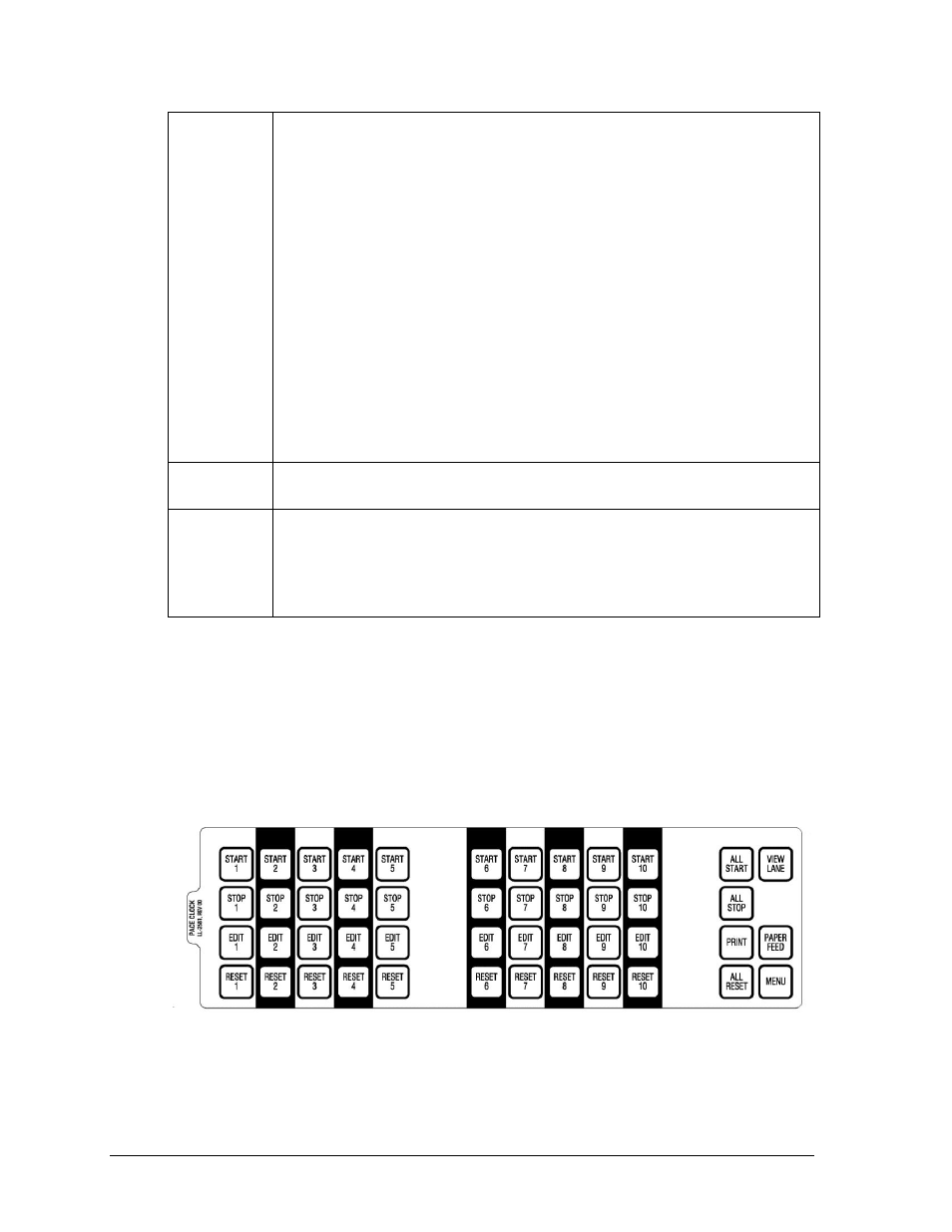
The Pace Clock keypad insert (LL-2581) is illustrated in Figure 180 and Drawing B-188395.
For general information about the keypad, refer to Section 3.2. The keys highlighted are
grouped together and shaded by lane. Lane 1 keys line-up vertically with Lane 1 on the LCD,
Lane 2 keys with Lane 2, and so on through Lane 10. The operator may perform four basic
functions by individual lane, or START, STOP or RESET ALL using the keys on the right.
Figure 180: Pace Clock Keypad Insert
