3 deck cabling & lane modules, Deck cabling & lane modules – Daktronics OmniSport 2000 Timing Console User Manual
Page 22
4
Timing System Setup
3. Bolts on newer touchpads
require only one 7/16" socket
wrench (Figure 4). Use two
7/16" wrenches to tighten
bolts on older touchpads
(Figure 5). Older systems
requiring two wrenches can be
updated to the new hardware
requiring only one wrench.
Call Daktronics to order the new hardware.
4. Connect the touchpads to the lane modules or deck plates. Read and follow
instructions in Section 2.3 before plugging the touchpads into the deck cabling.
5. A Daktronics touchpad is designed to fill with water to aid
in its stabilization. The touchpad seems to become a part of
the pool wall (Figure 6). If the pool wall has obstructions or
the gutter protrudes from the wall, use spacers (PVC board
may be cut in strips) to create a stable support for the
touchpad (Figure 7). Spacer size is determined by the height
and the extra depth required. Use 3M™ VHB™ Tape 5930
(Daktronics part number AT-1089 [¾"]) to connect the
touchpad to the spacers. Ensure the spacers do not cover
the drainage holes on the back of the touchpad!
Note: Daktronics does not provide
these spacers.
For more information on the care and maintenance
of touchpads, refer to Section 2.9. See also the
Daktronics T-7000 Series Touchpads Installation &
Maintenance Manual (DD1953274), available online
a
Do not allow swimmers to use paddles, fins or kick boards when touchpads are in the pool.
2.3 Deck Cabling & Lane Modules
Note: Always place cables and equipment in areas
of minimal traffic. Cover wires and cables with a mat to
prevent accidents. Figure 8 illustrates an important detail to
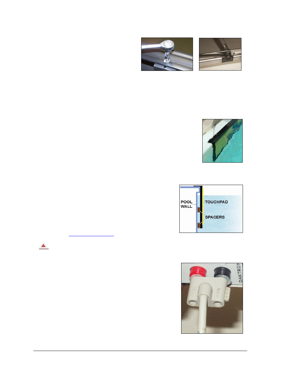
always remember when plugging dual banana connectors.
The GND (ground) tab on the plug must line up with the
black female jack for the timing system to work.
Remember this when connecting all dual banana plugs.
Figure 4: New Style Uses
One Wrench
Figure 5: Older Style
Uses Two Wrenches
Figure 6: Touchpad
Next to Wall
Figure 7: Touchpad with Spacers
Figure 8: Insert GND Side to
Black Female Jack