Ntp configuration, Upnp configuration, Desktop installation – Interlogix GE-DSSG-244-POE User Manual User Manual
Page 53: Lacp port status, Authentication configurati, Stack configuration, 10/100mbps, 10/100base-tx
IFS NS3601-24P/4S GE-DSSG-244 and 244-POE User Manual
51
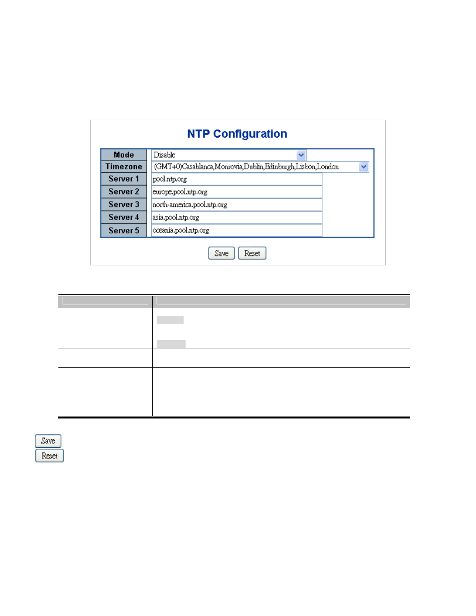
NTP Configuration
Configure NTP on this page.
NTP
is an acronym for Network Time Protocol, a network protocol for synchronizing the clocks of computer systems. NTP uses
UDP (data grams) as transport layer. You can specify NTP Servers and set GMT Time zone. The NTP Configuration screen is
shown
Figure 4-2-8
.
Figure 4-2-8
NTP
Configuration page screenshot
The page includes the following fields:
Object
Description
• Mode
Indicates the NTP mode operation. Possible modes are:
Enabled
: Enable NTP mode operation. When enable NTP mode operation, the
agent forward and to transfer NTP messages between the clients and the server
when they are not on the same subnet domain.
Disabled
: Disable NTP mode operation.
• Timezone
Allow select the time zone according to current location of switch.
•
Server #
Provide the NTP IPv4 or IPv6 address of this switch. IPv6 address is in 128-bit
records represented as eight fields of up to four hexadecimal digits with a colon
separates each field (:). For example, 'fe80::215:c5ff:fe03:4dc7'. The symbol '::' is
a special syntax that can be used as a shorthand way of representing multiple
16-bit groups of contiguous zeros; but it can only appear once. It also used a
following legally IPv4 address. For example, '::192.1.2.34'.
Buttons
: Click to save changes.
: Click to undo any changes made locally and revert to previously saved values.
UPnP Configuration
Configure UPnP on this page.
UPnP is an acronym for Universal Plug and Play. The goals of UPnP are to allow devices to connect seamlessly and to simplify the
implementation of networks in the home (data sharing, communications, and entertainment) and in corporate environments for
simplified installation of computer components. The UPnP Configuration screen is shown
Figure 4-2-9
.