15 hdlc/sdlc loop mode – Zilog Z16C30 User Manual
Page 88
5-21
Z16C30 USC
®
U
SER
'
S
M
ANUAL
Z
ILOG
UM97USC0100
5.15 HDLC/SDLC LOOP MODE
This mode applies only to the Transmitter. Software can
select it by programming the TxMode field of the Channel
Mode Register (CMR11-8) as 1110 while programming the
RxMode field (CMR3-0) as 0110 to select HDLC/SDLC
mode.
Loop mode is useful in networks in which the nodes or
stations form a physical loop. Except for one station that
acts in a “Primary” or Supervisory role, each must pass the
data it receives from the “preceding” station to the “follow-
ing” one. The only time that a secondary station can break
out of this echoing mode is when it receives a special
sequence called a “Go Ahead” and it has something to
send.
Again, this is a specific protocol and we can define how
certain other register fields should be programmed for its
intended application. For IBM SDLC Loop compatibility,
software should program the Transmit Mode Register
(TMR) as 6702
16
. This enables the Transmitter with NRZI-
Space encoding, 16-bit CCITT CRC, no parity, and 8-bit
characters. Software also should program the TxIdle field
in the Transmit Command/Status Register (TCSR10-8) as
000 to select Flags as the idle line state.
The two MSBits of the TxSubMode field (CMR15-14) con-
trol what the Transmitter does if an Underrun condition
occurs, that is, if it needs a character to send but the
TxFIFO is empty. The available choices are similar to those
in normal HDLC/SDLC mode but the Transmitter has a
wider range of subsequent actions:
14
13
12
11
10
9
8
7
6
5
4
3
2
1
0
15
TxResidue
RCCF
Ovflo
RCCF
Avail
Clear
RCCF
DPLL
Sync
DPLL
2Miss
DPLL
1Miss
DPLLEdge
On
Loop
Loop
Send
Resrvd
/TxACK /RxACK
CMR15-14
Response to Underrun
00
The Transmitter sends an Abort (“Go
Ahead”) sequence consisting of a zero
followed by seven consecutive ones, and
then stops sending and reverts to echoing
the data it receives. Zilog doesn’t recom-
mend this option in IBM SDLC Loop appli-
cations because only the Primary station
should issue a “Go Ahead” sequence (and
it should be in regular HDLC/SDLC mode).
01
Like 00 except that the Abort includes 15
ones.
10
The Transmitter sends Flags on an
Underrun, until another frame is ready or
until software clears CMR13 to 0.
11
The Transmitter sends its accumulated CRC
followed by Flags on an Underrun, until
another frame is ready to transmit or until
software clears CMR13 to 0. Zilog doesn’t
recommend this option either, because the
frame format probably hasn’t
been met when there’s an underrun.
The CMR13 bit plays a different role when the Transmitter
is first being enabled to “insert this station into the loop”, as
compared to normal operation after that. Before software
programs the Channel Mode Register for SDLC Loop
mode and enables the Transmitter, the TxD pin carries
continuous Ones. If software initially enables the Transmit-
ter with CMR13 0, it continues to output Ones on TxD.
When CMR13 is 1 after software first enables the Transmit-
ter, the channel sends Zeroes on TxD until the Receiver
detects a “Go Ahead” sequence (01111111). At this point
the channel starts passing data from RxD to TxD with a 4-
bit delay, and sets the OnLoop bit in the Channel Com-
mand/Status Register (CCSR7; see Figure 5-8).
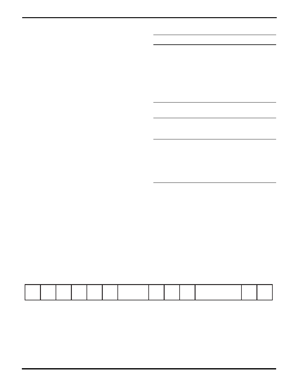
Figure 5-8. The Channel Command/Status Register (CCSR)
UM009402-0201