2 receive data interrupts – Zilog Z16C30 User Manual
Page 143
7-15
Z16C30 USC
®
U
SER
'
S
M
ANUAL
Z
ILOG
UM97USC0100
Abort/PE
If the IA bit for this source is 1, the interrupt
logic sets the RS IP bit when software or
the Receive DMA channel reads a char-
acter from the RxFIFO that failed parity
checking, or, in HDLC/SDLC mode with
the QAbort bit (RMR8) set, a character
that was followed by an Abort sequence.
RxOver
If the IA bit for this source is 1, the interrupt
logic sets the RS IP bit when software or
the Receive DMA channel reads a char-
acter from the RxFIFO that’s marked with
Overrun status. A character so marked is
the first one that arrived while the FIFO
was full. An indeterminate number of char-
acters after it may have been lost. See
‘Handling Overruns and Underruns’ in
Chapter 5 for more information.
As described in Chapter 5, once an Interrupt-Armed RCSR
bit has been set, it must be “unlatched” by writing a 1 to that
bit position in the RCSR. For Exited Hunt, Abort (in HDLC
mode), RxBound, Abort/PE, and RxOver, this action also
clears the RCSR bit. The IdleRcved and Break/Abort (in
async modes) bits in RCSR don’t become 0 until software
has unlatched the bit and the line condition has ended.
Each of these six sources has a separate
Interrupt Arm
(IA)
bit in the LSByte of the Receive Interrupt Control
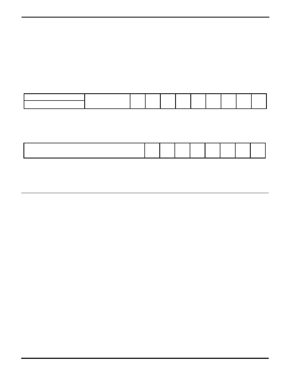
Register (RICR). Figure 7-10 shows the RICR. If an IA bit is
1, the interrupt logic can set the Receive Status IP bit as
described above. If an IA bit is 0, the corresponding bit in
RCSR has no effect on the IP bit and thus will not cause
interrupts. The setting of the IA bits for the ExitedHunt,
IdleRcved, and Break/Abort conditions has no effect on
the bits in RCSR, while the IA bits for the RxBound, Abort/
PE, and Overrun conditions affect how the corresponding
RCSR bits operate, as described in Chapter 5.
In order to ensure that future interrupts are requested
properly when more than one Receive Status condition is
Armed in the RICR, a Receive Status interrupt service
routine must clear all of the IA bits in the RICR and then set
the desired ones again, after it has cleared the RS IP bit
and the RCSR bits that it has serviced.
When software wants to change the IA bits in the RICR after
the register is first initialized, it should write only the LS byte
of the register rather than all 16 bits, to avoid inadvertently
changing a threshold setting in the MS byte.
7.11.2 Receive Data Interrupts
This interrupt type has only one source, so there’s no IA bit
for it. The interrupt logic sets the
RD IP
bit when a character
is received and the number of previously-received charac-
ters in the RxFIFO is equal to the number programmed as
the “Receive Data Interrupt Request Level”. That is, the IP
bit is set for the character that makes the number of
characters in the RxFIFO exceed the programmed value.
The RD IP bit is also set if the number of characters is less
than the programmed threshold level, and the receiver
places a character marked with RxBound status in the
RxFIFO.
If received data is handled by either software polling or an
external Receive DMA channel, disable the Receive Data
interrupt by leaving its IE bit 0. (A later section discusses
IE bits.)
14
13
12
11
10
9
8
7
6
5
4
3
2
1
0
15
Exited
Hunt
Idle
Rcved
Break
/Abort
Rx
Bound
CRCE
/FE
Abort
/PE
RX
Over
Rx
Avail
RCmd(WO)
2ndBE
1stBE
RxResidue
ShortF/
CVType
Figure 7-9. The Receive Command/Status Register (RCSR)
14
13
12
11
10
9
8
7
6
5
4
3
2
1
0
15
Exited
Hunt IA
Idle
Rcved
IA
Break
/Abort
IA
Rx
Bound
IA
Word
Status
Abort
/PE
IA
RXOver
IA
TCOR
Sel
"RxFIFO fill level" if last RCSR 15-12 command 4-7 was 5
"Rx Int Req level" if last RCSR 15-12 command 4-7 was 6
"Rx DMA Req level" If last RCSR 15-12 command 4-7 was 7
Figure 7-10. The Receive Interrupt Control Register (RICR)
UM009402-0201