Zilog Z16C30 User Manual
Page 185
8-30
Z16C30 USC
®
U
SER
'
S
M
ANUAL
Z
ILOG
UM97USC0100
14
13
12
11
10
9
8
7
6
5
4
3
2
1
0
15
RxCDn
IA
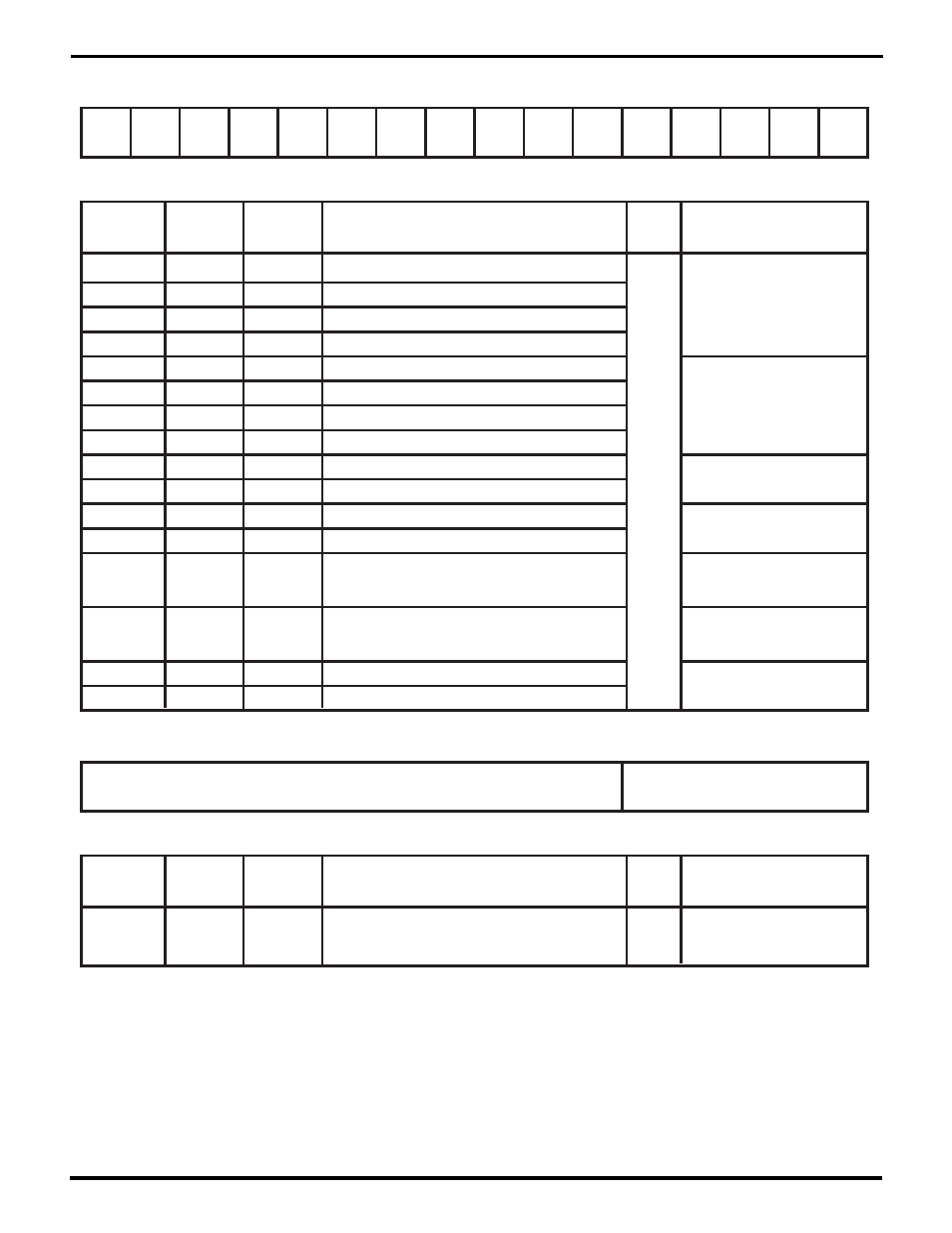
Status Interrupt Control Register (SICR)
Register Address 0 b 01111
Bit(s)
Field/Bit
Name
Conditions
/Context
Description
RW
Status
Ref Chapter: Section
SICR15
RxCDn IA
RW
4: The /RxC and /TxC Pins
RxCUp
IA
TxCDn
IA
TxCUp
IA
RxRDn
IA
RxRUp
IA
TxRDn
IA
TxRUp
IA
DCDDn
IA
DCDUp
IA
CTSDn
IA
CTSUp
IA
RCC
Under
IA
DPLL
DSync
IA
BRG1
IA
BRG0
IA
1=set MISR15/interrupt on fall of /RxC
SICR14
RxCUp IA
1=set MISR15/interrupt on rise of /RxC
SICR13
TxCDn IA
1=set MISR13/interrupt on fall of /TxC
SICR12
TxCUp IA
1=set MISR13/interrupt on rise of /TxC
SICR11
RxRDn IA
1=set MISR11/interrupt on fall of /RxREQ
SICR10
RxRUp IA
1=set MISR11/interrupt on rise of /RxREQ
SICR9
TxRDn IA
1=set MISR9/interrupt on fall of /TxREQ
SICR8
TxRUp IA
1=set MISR9/interrupt on rise of /TxREQ
4: /RxREQ and /TxREQ Pins
4: The /DCD Pin
SICR7
DCDDn IA
1=set MISR7/interrupt on fall of /DCD
SICR6
DCDUp IA
1=set MISR7/interrupt on rise of /DCD
SICR5
CTSDn IA
1=set MISR5/interrupt on fall of /CTS
SICR4
CTSUp IA
1=set MISR5/interrupt on rise of /CTS
SICR3
RCC Under
IA
1=interrupt on RCC undflow
(Receive frame/message longer than
max allowed)
4: The /CTS Pin
5: DMA Support Features:
The RCC FIFO
RCC used
SICR2
DPLLDSync
IA
1=interrupt on DPLL sync loss
4: More About the DPLL
7: Miscellaneous Interrupt
Sources and IA Bits
Biphase
SICR1
BRG1 IA
1=interrupt on BRG1 zero
SICR0
BRG0 IA
1=interrupt on BRG0 zero
4: Tx and Rx Clocking:
The Baud Rate Generators
14
13
12
11
10
9
8
7
6
5
4
3
2
1
0
15
Reserved (0)
Test Mode Control Register (TMCR)
Register Address 0 b 00111
Bit(s)
Field/Bit
Name
Conditions
/Context
Description
RW
Status
Ref Chapter: Section
Test Register Address
TMCR4-0
Address of test register to read and write in TMDR
RW
8: Test Modes
RW = Read/Write, RO = Read Only, WO = Write Only – for other codes see p. 8-10.
UM009402-0201