8 the /dcd pin (continued) – Zilog Z16C30 User Manual
Page 63
4-14
Z16C30 USC
®
U
SER
'
S
M
ANUAL
UM97USC0100
Z
ILOG
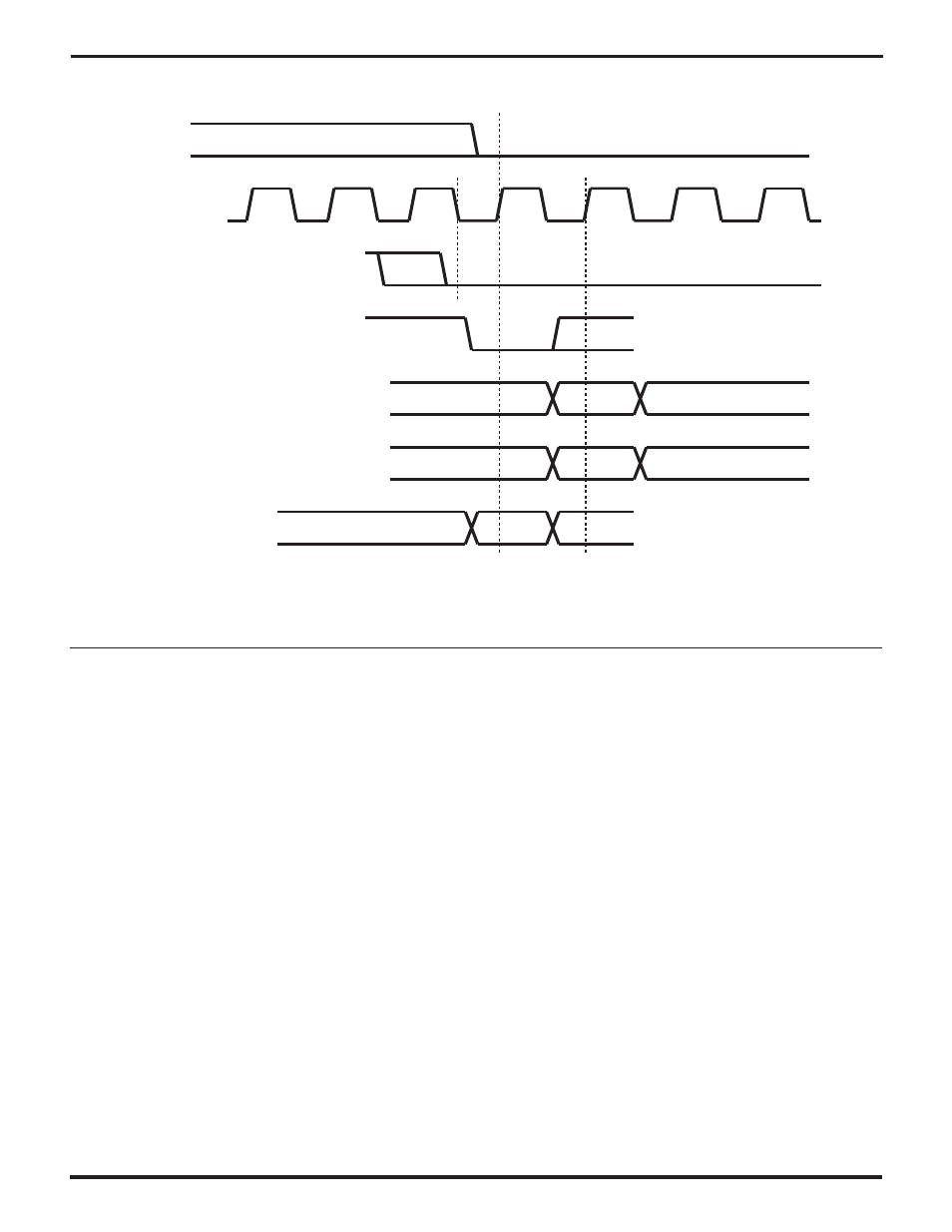
4.8 THE /DCD PIN
(Continued)
/DCD
RxCLK
(/RxC)
RxD (Async, 9-Bit
ACV/1553B
RxD (Isochronous)
RxD (External Sync)
RxD (Monosync, Bisync,
Transparent Bisync)
RxD (HDLC)
0111111
Last 0
of Flag
1st Bit
of Frame
1st Bit
of Sync
Rest of Sync Character(s)
1st Bit
Received
Start
Bit
Start Bit
Figure 4-9. /DCD Auto-Enable Timing
Software can program a channel to interrupt the host
processor on either or both edges on /DCD, as described
in the preceding section. Typically such interrupts would
be used when /DCD is an input, that is, when DCDMode is
00 or 01. Software should write a 1 to the
DCDDn IA
bit in
the Status Interrupt Control Register (SICR7) to make a
channel detect falling edges on /DCD, and write a 1 to
DCDUp
IA (SICR6) to make it detect rising edges.
As described in the preceding section, the
DCDL/U
bit
(MISR7) is 1 if the channel has detected an enabled edge,
until software writes a 1 to the bit to clear it. The
/DCD
bit
(MISR6) reflects the state of the /DCD pin transparently
while DCDL/U is 0, but is frozen while DCDL/U is 1.
MISR6=0 indicates a high on the pin, and 1 indicates a low.
UM009402-0201