Zilog Z16C30 User Manual
Page 141
7-13
Z16C30 USC
®
U
SER
'
S
M
ANUAL
Z
ILOG
UM97USC0100
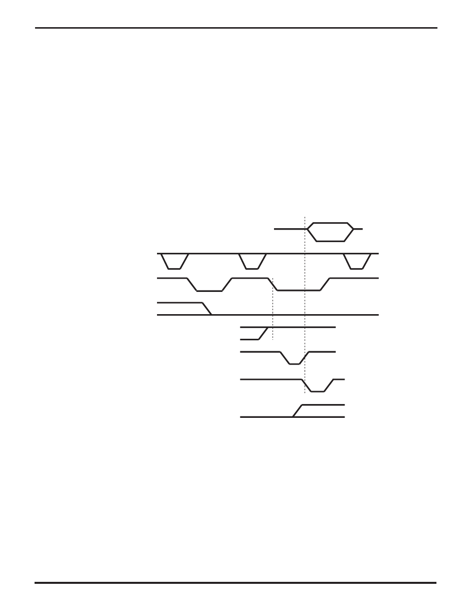
Figure 7-8 shows the kind of interrupt acknowledge cycle
that the USC expects when /PITACK goes low and the
2PulseIACK bit (BCR1) is 1. Here, two consecutive low
pulses on /PITACK constitute the complete interrupt ac-
knowledge cycle, and /DS and /RD should both stay high
throughout the cycle. This mode is compatible with several
microprocessors made by Intel Corp. and other compa-
nies. As in the preceding case, operation is similar whether
the bus is multiplexed or non-multiplexed. The multiplexed
bus must meet minimum times between the pulses on /AS
and the pulses on /PITACK. These minima are similar to
those between /AS and /DS or /RD in register read cycles.
In “double pulse mode” the channel keeps an internal state
bit that distinguishes the two /PITACK pulses in each pair.
The channel freezes its internal interrupt state in response
to the first falling edge on /PITACK. If it is requesting an
interrupt it forces its IEO output low regardless of the state
of IEI, and starts resolving its internal interrupt priorities,
but the channel does not otherwise respond to the first
cycle.
In this mode the IEI pin must be valid for a specified setup
time before /PITACK goes low for the second pulse. If IEI
is high at this point and the channel is requesting an
interrupt, it responds to the second /PITACK pulse by
setting the IUS bit of its highest-priority requesting type of
interrupt, driving a vector onto the AD7-0 pins, and driving
/WAIT//RDY appropriately to signal when the vector is
valid. If IEI is low at the leading edge of /PITACK, and/or if
the channel is not requesting an interrupt, it doesn’t re-
spond to the cycle.
AD15-AD0
vector
/AS
/PITACK
IEO
/WAIT//RDY
(as Wait)
/WAIT//RDY
(as Ack)
/INT
IEI
Figure 7-8. A /PITACK Interrupt Acknowledge Cycle with 2PulseIACK=1
UM009402-0201