Zilog Z16C30 User Manual
Page 173
8-18
Z16C30 USC
®
U
SER
'
S
M
ANUAL
Z
ILOG
UM97USC0100
14
13
12
11
10
9
8
7
6
5
4
3
2
1
0
15
BRG0Src
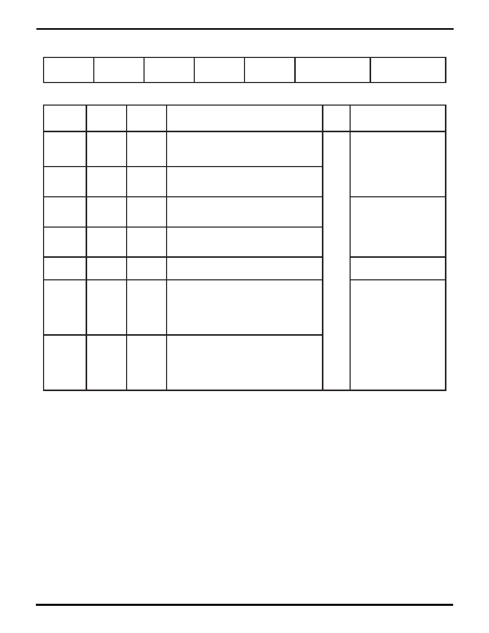
Clock Mode Control Register (CMCR)
Register Address 0 b 01000
Bit(s)
Field/Bit
Name
Conditions
/Context
Description
RW
Status
Ref Chapter: Section
RxCLKSrc
CMCR15-14
TxCLKSrc
DPLLSrc
BRG1Src
CTR0Src
CTR1Src
CTR1Src
00=CTR1 disabled;
10=/RxC pin; 11=/TxC pin
RW
4: Tx and Rx Clocking;
CTR0 and CTR1
CMCR13-12
CTR0Src
00=CTR0 disabled;
10=/RxC pin; 11=/TxC pin
CMCR11-10
BRG1Src
00=BRG1 input is CTR0 output;
01=CTR1 output; 10=/RxC pin; 11=/TxC pin
CMCR9-8
BRG0Src
00=BRG0 input is CTR0 output or;
01=CTR1 output; 10=/RxC pin; 11=/TxC pin
4: Tx and Rx Clocking;
The Baud Rate Generators
CMCR7-6
DPLLSrc
00=DPLL input is BRG0 output;
01=BRG1 output; 10=/RxC pin; 11=/TxC pin
4: Tx and Rx Clocking;
Introduction to the DPLL
CMCR5-3
TxCLKSrc
000=no TxCLK (Transmit disabled);
001=TxCLK is /RxC; 010=/TxC;
011=DPLL Tx output;
100=BRG0 output; 101=BRG1 output;
110=CTR0 output;
111=TxCLK is CTR1 output
4: Tx and Rx Clocking;
TxCLK and RxCLK Selection
CMCR2-0
RxCLKSrc
000=no RxCLK (Receive disabled);
001=RxCLK is /RxC; 010=/TxC;
011=DPLL Rx output;
100=BRG0 output; 101=BRG1 output;
110=CTR0 output;
111=RxCLK is CTR1 output
RW = Read/Write, RO = Read Only, WO = Write Only – for other codes see p. 8-10.
UM009402-0201