Zilog Z16C30 User Manual
Page 179
8-24
Z16C30 USC
®
U
SER
'
S
M
ANUAL
Z
ILOG
UM97USC0100
14
13
12
11
10
9
8
7
6
5
4
3
2
1
0
15
RxCL/U
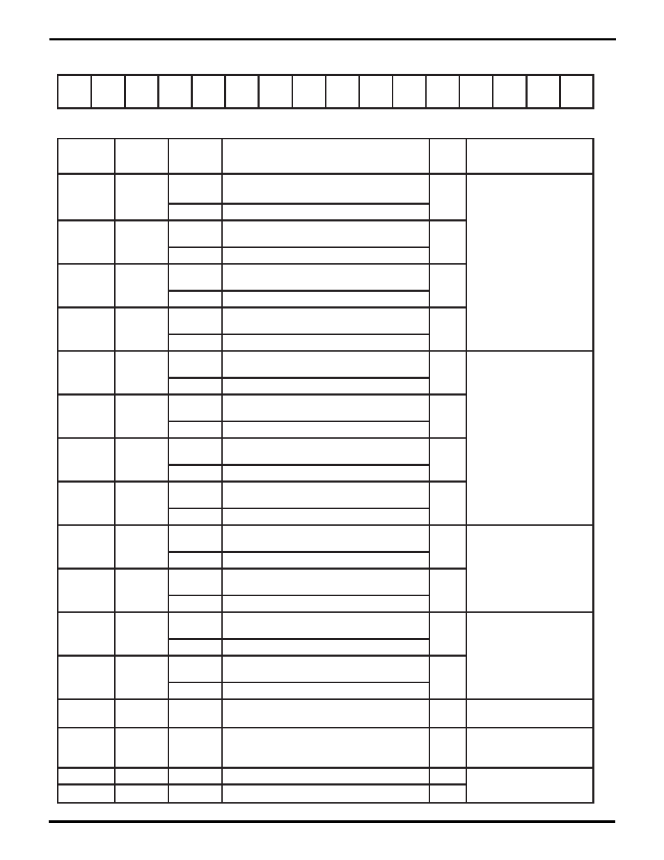
Miscellaneous Interrupt Status Register (MISR)
Register Address 0 b 01110
Bit(s)
Field/Bit
Name
Conditions
/Context
Description
RW
Status
Ref Chapter: Section
BRG0
L/U
MISR15
BRG1
L/U
/RxC
TxCL/U
/TxC
RxRL/U
/RxR
TxRL/U
/TxR
DCDL/U
/DCD
CTSL/U
/CTS
RCC
Under
L/U
DPLL
DSync
L/U
RxCL/U
Read
1=one or more transition(s) enabled by SICR15-14
has (have) occurred on the /RxC pin
R,W1U
4: The /RxC and /TxC Pins
Write
1=open the latches for /RxC and for this bit
MISR14
/RxC
RxCL/U=1
1=the (first such) enabled transition was a rising edge;
0=it was a falling edge
RO
RxCL/U=0
1=the /RxC pin is low; 0=it's high
MISR13
TxCL/U
Read
1=one or more transition(s) enabled by SICR13-12
has (have) occurred on the /TxC pin
Write
1=open the latches for /TxC and for this bit
R,W1U
MISR12
/TxC
TxCL/U=1
1=the (first such) enabled transition was a rising edge;
0=it was a falling edge
TxCL/U=0
1=the /TxC pin is low; 0=it's high
RO
MISR11
RxRL/U
Read
1=one or more transition(s) enabled by SICR11-10
has (have) occurred on the /RxREQ pin
R,W1U
4: The /RxREQ and /TxREQ
pins
Write
1=open the latches for /RxR and for this bit
MISR10
/RxR
RxRL/U=1
1=the (first such) enabled transition was a rising edge;
0=it was a falling edge
RO
RxRL/U=0
1=the /RxREQ pin is low; 0=it's high
MISR9
TxRL/U
Read
1=one or more transition(s) enabled by SICR9-8
has (have) occurred on the /TxREQ pin
Write
1=open the latches for /TxR and for this bit
R,W1U
MISR8
/TxR
TxRL/U=1
1=the (first such) enabled transition was a rising edge;
0=it was a falling edge
TxRL/U=0
1=the /TxREQ pin is low; 0=it's high
RO
MISR7
DCDL/U
Read
1=one or more transition(s) enabled by SICR7-6
has (have) occurred on the /DCD pin
Write
1=open the latches for /TxR and for this bit
R,W1U
4: The /DCD Pin
MISR6
/DCD
DCDL/U
1=the (first such) enabled transition was a rising edge;
0=it was a falling edge
DCDL/U=0
1=the /DCD pin is low; 0=it's high
RO
MISR5
CTSL/U
Read
1=one or more transition(s) enabled by SICR5-4
has (have) occurred on the /CTS pin
Write
1=open the latches for /CTS and for this bit
R,W1U
4: The /CTS Pin
MISR4
/CTS
CTSL/U=1
1=the (first such) enabled transition was a rising edge;
0=it was a falling edge
CTSL/U=0
1=the /CTS pin is low; 0=it's high
RO
MISR3
RCC Under
L/U
1=RCC FIFO has counted down past 0
(Receive frame/message longer than max allowed)
R,W1U
5: DMA Support Features:
The RCC FIFO
MISR2
DPLLDSync
L/U
1=DPLL has lost sync
R,W1U
4: More About the DPLL
7: Miscellaneous Interrupt
Sources and IA Bits
MISR1
BRG1 L/U
1=BRG1 has counted down to 0
R,W1U
4: Tx and Rx Clocking:
The Baud Rate Generators
MISR0
BRG0 L/U
1=BRG0 has counted down to 0
R,W1U
RW = Read/Write, RO = Read Only, WO = Write Only – for other codes see p. 8-10.
UM009402-0201