7 edge detection and interrupts (continued) – Zilog Z16C30 User Manual
Page 61
4-12
Z16C30 USC
®
U
SER
'
S
M
ANUAL
UM97USC0100
Z
ILOG
4.7 EDGE DETECTION AND INTERRUPTS
(Continued)
While an L/U bit is 1, the state of the associated data bit is
frozen (latched). These two bits remain in this state, re-
gardless of further transitions on the pin, until software
writes a 1 to the L/U bit. This clears the L/U bit to 0 and
“opens” the data latch to once again report and track the
state of the pin, at least for an “instant”. If one or more
enabled transitions occurred while the L/U bit was set, then
L/U is set again right after software writes the 1 to it.
Writing a 0 to an L/U bit has no effect, and the channel
ignores data written to the “data” bits.
One mode in which software can use this logic is to read
the MISR, then immediately write back what it has read.
The software should then look for 1’s in any and all
“interesting” L/U bits, and process/handle all such changes
without rereading the MISR. To obtain the current state of
one of these pins, regardless of the L/U bit, software can
write a 1 to the L/U bit and then immediately read back the
MISR.
RxCUp
IA
14
13
12
11
10
9
8
7
6
5
4
3
2
1
0
15
RxCDn
IA
TxRDn
IA
TxCDn
IA
CTSUp
IA
DCDDn
IA
RCC
Under
IA
TxCUp
IA
RxRDn
IA
RxRUp
IA
TxRUp
IA
DCDUp
IA
CTSDn
IA
DPLL
DSync
IA
BRG1
IA
BRG0
IA
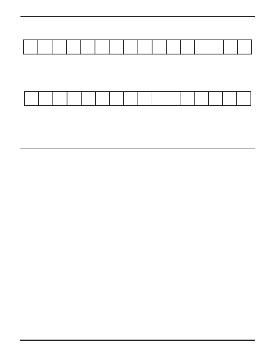
Figure 4-7. The Status Interrupt Control Register (SICR)
/RxC
14
13
12
11
10
9
8
7
6
5
4
3
2
1
0
15
RxCL/U
TxRL/U
TxCL/U
/CTS
DCDL/U
RCC
Under
L/U
/TxC
RxRL/U /RxREQ
/TxREQ
/DCD
CTSL/U
DPLL
DSync
L/U
BRG1
L/U
BRG0
L/U
Figure 4-8. The Miscellaneous Interrupt Status Register (MISR)
UM009402-0201