2 the baud rate generators (continued) – Zilog Z16C30 User Manual
Page 53
4-4
Z16C30 USC
®
U
SER
'
S
M
ANUAL
UM97USC0100
Z
ILOG
4.3.2 The Baud Rate Generators
(Continued)
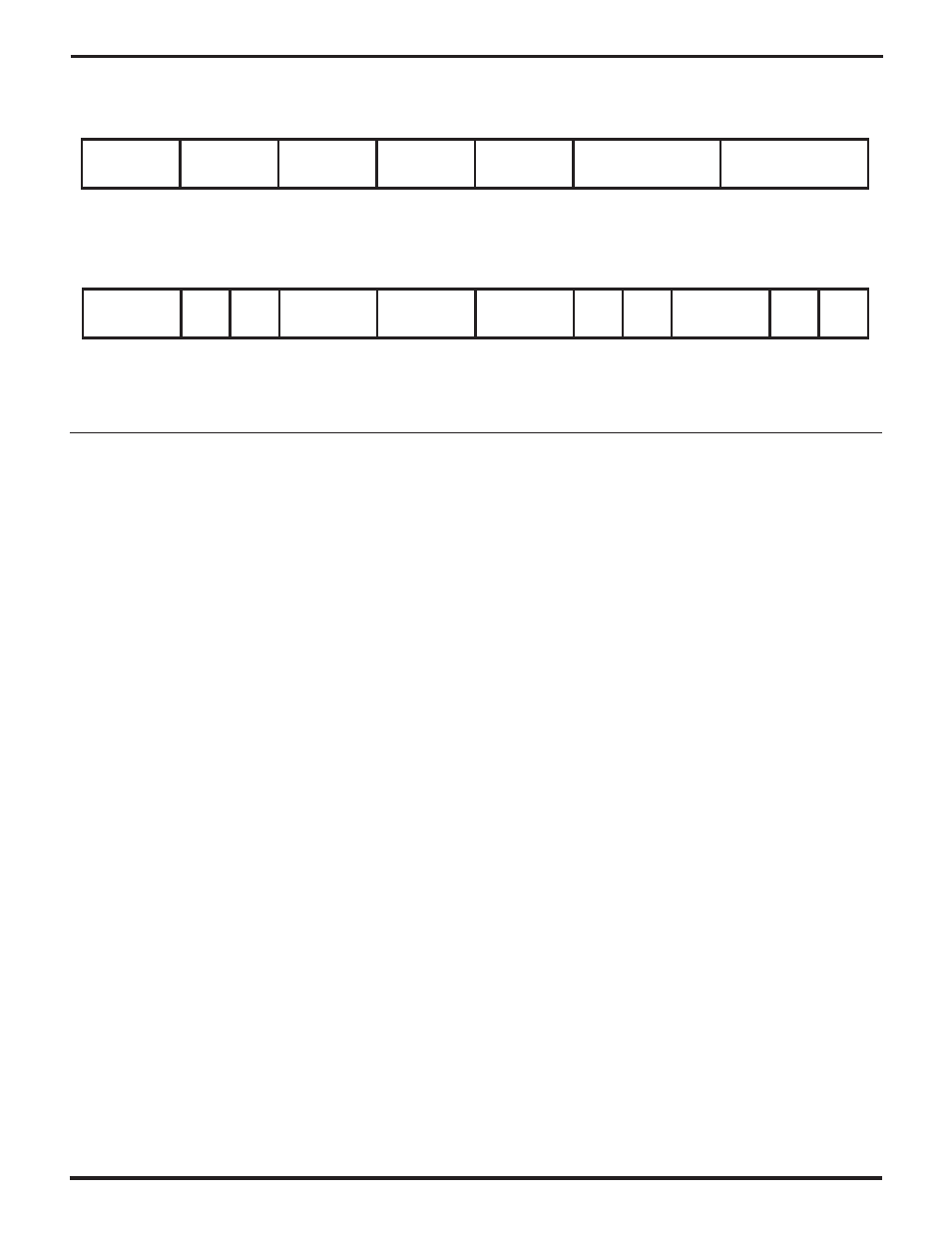
RxCLKSrc
CTR1Src
14
13
12
11
10
9
8
7
6
5
4
3
2
1
0
15
TxCLKSrc
DPLLSrc
BRG0Src
BRG1Src
CTR0Src
Figure 4-2. The Clock Mode Control Register (CMCR)
CTR0Div
14
13
12
11
10
9
8
7
6
5
4
3
2
1
0
15
CTR1
DSel
CVOK
DPLLDiv
DPLLMode
TxAMode
BRG1S BRG1E
RxAMode
BRG0S BRG0E
Figure 4-3. The Hardware Configuration Register (HCR)
Each of the two Time Constant registers (
TC0R
and
TC1R
)
contains a 16-bit starting value for the corresponding BRG
down-counter. Zero in a Time Constant Register makes a
BRG’s output clock identical with its input clock; a value of
one makes a BRG divide its input clock by two, and so on
— the all-ones value makes a BRG divide its input clock by
65,536 to produce its output clock. This flexibility of divid-
ing by any value means that a channel can derive almost
any baud rate from almost any input clock, unlike some
competing devices that constrain the system designer to
use specified crystal or oscillator values and constrain the
available speeds to certain commonly-used baud rates.
The
BRG0E
and
BRG1E
bits in the Hardware Configura-
tion Register (HCR0 and HCR4 respectively; the “E” in the
names is for “Enable”) control whether each Baud Rate
Generator runs or not. A 0 in one of these bits inhibits/
blocks down-counting by the corresponding BRG, keep-
ing the current value in the down counter unchanged
despite transitions on the selected input clock. A 1 in one
of these bits enables the corresponding BRG to count
down in response to input clock transitions.
When a Baud Rate Generator counts down to zero, it sets
the
BRG0L/U
or
BRG1L/U
bit in the Miscellaneous Inter-
rupt Status Register (MISR1 or 0). Once one of these bits
is set, it stays set until software writes a 1 to the bit, to
“unlatch” it”.
A BRG may or may not continue to operate after counting
down to zero, depending on the
BRG0S
or
BRG1S
bit in
the Hardware Configuration Register (HCR1 or HCR5
respectively; the “S” stands for “Single cycle”). A 0 in
BRGnS causes BRGn to reload the TCn value automati-
cally and continue operation, while BRGnS=1 makes BRGn
stop when it reaches 0.
Software can (re)load the value in the Time Constant
register(s) into one or both BRG counters by writing a
"Load TC0", "Load TC1", or "Load TC0 and TC1" command
to the RTCmd field of the Channel Command/Address
Register (CCAR15-11), as described in the Commands
section of Chapter 4. These commands also restart a BRG
that’s in Single Cycle mode and has counted down to zero
and stopped.
The
TC0RSel
bit in a channel’s Receive Interrupt Control
Register (RICR0) and the
TC1RSel
bit in its Transmit
Interrupt Control Register (TICR0) control what data the
channel provides when software reads the TC0R and
TC1R register addresses. If a TCnRSel bit is 0, the channel
returns the time constant value last written to TCn. When a
1 is written to a TCnRSel bit, the channel captures the
current value of the BRGn counter into a special latch, and
thereafter returns the captured value from this latch when
software reads the TCn address. Note that in order to
obtain a series of relatively current values of a running
BRGn, software has to write a 1 to the TCnRSel bit just
before each time it reads the TCn location.
UM009402-0201