4 bit oriented synchronous modes – Zilog Z16C30 User Manual
Page 71
5-4
Z16C30 USC
®
U
SER
'
S
M
ANUAL
UM97USC0100
Z
ILOG
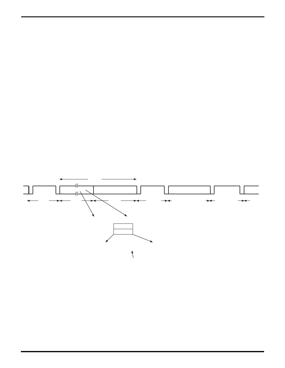
May be Flags, Mark,
Space, or Not Driven
Data
Flag
(7E)
Flag
(7E)
CRC
Data
Flag
(7E)
Frame
Suppose that the Data presented to the Transmitter includes:
1110xxxx
yy100111
The Data actually sent will include:
x01111101001y
Extra 0-bit inserted by Transmitter,
deleted by Receiver
Figure 5-3. HDLC/SDLC Data
5.4 BIT ORIENTED SYNCHRONOUS MODES
As character-oriented synchronous protocols came into
wider use in the 1960’s and 70’s, the number of characters
having special significance for the hardware kept increas-
ing. Hand in hand with this, the complexity of the required
hardware processing and state machines rose drastically.
Particularly troublesome was data “transparency”, the
ability to transmit any kind of “binary” data without conflict
with the various control characters used in these protocols.
These problems might be less severe were they occurring
today. But given the technology available in the 1960’s, the
proliferation of sync protocols was making it harder and
harder to build general-purpose datacom hardware. In-
stead, one had to build dedicated communications con-
trollers for each protocol.
Bit oriented synchronous protocols were a response to
these problems. IBM’s SDLC was the first one widely used;
subsequent standardization efforts added several refine-
ments in defining HDLC. These protocols simultaneously
minimized the amount of required hardware support, while
lifting all restrictions on the content of the data transmitted.
Figure 5-3 shows how in bit-oriented modes, a frame is a
group of sequential characters ending with a CRC code to
verify its correctness, as in character-oriented protocols.
The difference lies in the Flag sequences used to begin,
end, and separate frames.
When a bit-oriented synchronous Receiver starts to re-
ceive a frame, it looks for a Flag sequence (01111110) just
as a character-oriented synchronous Receiver looks for its
sync character. While sending a frame, a bit-oriented
synchronous Transmitter continually checks whether any
sequence of data bits could look like a Flag. It does this
without regard for character boundaries. Whenever the
data presented to a Transmitter includes a zero followed
by five ones, the Transmitter adds an extra zero-bit after
the fifth one-bit. Correspondingly, a bit-oriented synchro-
nous Receiver monitors the serial data stream within a
frame; any time it sees 0111110, regardless of character
boundaries, it deletes the trailing zero.
UM009402-0201