Zilog Z16C30 User Manual
Page 140
7-12
Z16C30 USC
®
U
SER
'
S
M
ANUAL
UM97USC0100
Z
ILOG
7.9 INTERRUPT ACKNOWLEDGE CYCLES
(Continued)
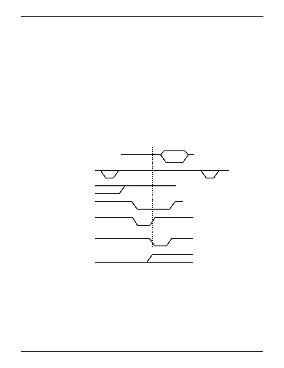
Figure 7-7 shows the kind of interrupt acknowledge cycle
that the USC expects when /PITACK goes low and the
2PulseIACK bit (BCR1) is 0. Here a single pulse on
/PITACK substitutes for the pulse on /DS or /RD in the
previous cases; the latter two signals must remain high
throughout the cycle. For this case, operation on a non-
multiplexed bus is identical with that on a multiplexed bus
once the /AS strobe is over. The only distinction is that a
multiplexed bus must meet minimum times between the
pulse on /PITACK and the preceding and following pulses
on /AS. These minima are similar to those required for
register read and write cycles.
In this mode, an interrupt acknowledge daisy chain on
IEI/IEO cannot be used to select whether an USC channel
or another device should respond to each interrupt ac-
knowledge cycle. Instead, external logic like that shown in
Figure 7-2 must decide which requesting device/channel
is to respond to an interrupt acknowledge cycle, if such a
cycle occurs when more than one is requesting an inter-
rupt. The external logic would typically consider the state
of the individual devices’/channels’ interrupt request lines
in making this decision. (The lines cannot be OR-tied in this
case.)
In this “single-pulse” mode, the IEI pin must set up and
hold around the leading/falling edge on /PITACK. If IEI is
high and the channel is requesting an interrupt at that
point, it responds to /PITACK by driving a vector onto the
AD7-0 pins and driving /WAIT//RDY appropriately to signal
when the vector is valid. If IEI is low at the leading/falling
edge of /PITACK, and/or if the channel is not requesting an
interrupt at that point, it doesn’t respond to the cycle.
AD15-AD0
vector
/AS
IEI
/PITACK
/WAIT//RDY
(as Wait)
/WAIT//RDY
(as Ack)
/INT
Figure 7-7. A /PITACK Interrupt Acknowledge Cycle with 2PulseIACK=0
UM009402-0201