Zilog Z16C30 User Manual
Page 184
8-29
Z16C30 USC
®
U
SER
'
S
M
ANUAL
Z
ILOG
UM97USC0100
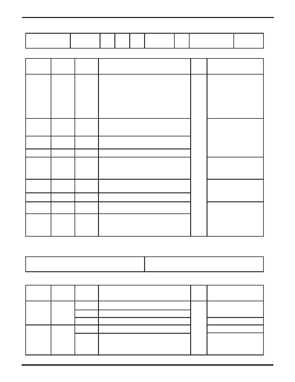
RxDecode
Receive Mode Register (RMR)
Register Address 0 b 10001
RxPar
Enab
RxCRCType
RxCRC
Start
RxCRC
Enab
QAbort
RxParType
RxLength
RxEnable
14
13
12
11
10
9
8
7
6
5
4
3
2
1
0
15
Receive Sync Register (RSR)
Register Address 0 b 10100
Bit(s)
Field/Bit
Name
Conditions
/Context
Description
RW
Status
Ref Chapter: Section
RSR15-8
Receive Sync, SYN1, or 9th-16th bits of Ethernet address
Receive SYN0 or 1st-8th bits of address
Receive Sync match character
WR
5: Monosync and Bisync Modes
Monosync
second half of Receive sync match (SYN1)
Bisync
match against last-received 8 bits of address
802.3
RSR7-0
first half of Receive sync match (SYN0)
5: Monosync and Bisync Modes
Bisync
match against first-received 8 bits of address
H/SDLC,
(CMR7-4)
not xx00,
or 802.3
5: 802.3 (Ethernet) Mode
5: HDLC/SDLC Mode
5: 802.3 (Ethernet) Mode
Bit(s)
Field/Bit
Name
Conditions
/Context
Description
RW
Status
Ref Chapter: Section
RMR15-13
RxDecode
000=RxD not encoded ("NRZ");
001=invert polarity of RxD ("NRZB");
010=decode RxD NRZI-Mark;
011=decode RxD NRZI-Space;
100=decode RxD Biphase-Mark (FM1);
101=decode RxD Biphase-Space (FM0);
110=decode RxD Biphase-Level (Manchester);
111=decode RxD Differential Biphase-Level
RW
4: Data Formats and
Encoding
RMR12-11
RxCRCType
00=use 16-bit CRC-CCITT for Rx;
01=use CRC-16 for Rx;
10=use 32-bit Ethernet CRC for Rx
5: Cyclic Redundancy
Checking
Sync
RMR10
RxCRCStart
0=start Receive CRC generator as all-zeros;
1=all ones
Sync
RMR9
RxCRCEnab
1=include Receive characters in CRC
Sync
RMR8
QAbort
0=use Abort/PE bit in RxFIFO, RCSR2 for
Abort indication; 0=use it for Parity Error indication
5: Status Reporting: Detailed
Status in RCSR
5: HDLC/SDLC: Handling a
Received Abort
HDLC/
SDLC
RMR7-6
RxParType
00=Receive Parity Even; 01=Odd;
10=Zero (Space); 11=One (Mark)
5: Parity Checking
RMR5
RxParEnab
1=accumulate and check Parity bits
RMR4-2
RxLength
000=receive eight bit characters;
001-111=receive 1-7 bit characters
5: The Mode Registers:
Character Length
RMR1-0
RxEnable
00=disable Receiver (immediately);
01=disable Rx at end of message/frame/char;
10=enable Rx unconditionally;
11=auto-enable Rx per /DCD pin
14
13
12
11
10
9
8
7
6
5
4
3
2
1
0
15
RW = Read/Write, RO = Read Only, WO = Write Only – for other codes see p. 8-10.
UM009402-0201