Zilog Z16C30 User Manual
Page 83
5-16
Z16C30 USC
®
U
SER
'
S
M
ANUAL
UM97USC0100
Z
ILOG
5.13 IEEE 802.3 (ETHERNET) MODE
Software can select this mode for the Transmitter and the
Receiver, by programming 1001 into the TxMode and
RxMode fields of the Channel Mode Register (CMR11-8
and CMR3-0).
The USC’s capabilities for handling Ethernet communica-
tions are less comprehensive than those offered by various
dedicated Ethernet controllers. In particular, external hard-
ware must detect collisions and generate the pseudo-
random “backoff” timing when a collision occurs. In Ethernet
parlance, blocks of consecutive characters are called
"frames" rather than messages.
Since Ethernet is a relatively specific, well-defined proto-
col we can define the proper settings for many of the
channel’s register fields and options. We can specify the
exact values that software should program into the Trans-
mit Mode Register (D703
16
) and Receive Mode Register
(D603
16
). These values specify Bi-phase-Level encoding,
a 32-bit CRC sent at End of Frame, no parity, and 8-bit
characters, all according to Ethernet practise and IEEE
802.3. In addition the 2 LSBits specify auto-enabling
based on signals from external hardware on /CTS and
/DCD.
On the transmit side,
software should program the TxPreL
and TxPrePat fields of the Channel Control Register (CCR11-
8) to 1110. This value makes the Transmitter send the 64-
bit Preamble pattern 1010... before each frame. In 802.3
mode the Transmitter automatically changes the 64th bit
from 0 to 1 to act as the “start bit”.
Furthermore, software should program the TxIdle field of
the Transmit Command/Status Register (TCSR10-8) to 110
or 111. These values select an Idle line condition of
constant Space or Mark. This condition, in turn, allows
external logic to detect the missing clock transition in the
first bit after the end of the CRC, and turn off its transmit line
driver. (In a low-cost variant, such an Idle state can simply
disable an open-collector or similar unipolar driver.) An-
other alternative is to use the Tx Complete output on /TxC
to control the driver.
External logic must detect collisions that may occur while
the channel is sending, and signal the Transmitter by
driving the /CTS pin high when this occurs. Besides the
auto-enable already noted for TMR1-0, software should
write the CTSMode field of the Input/Output Control Reg-
ister (IOCR15-14) as 0x to support this use of /CTS.
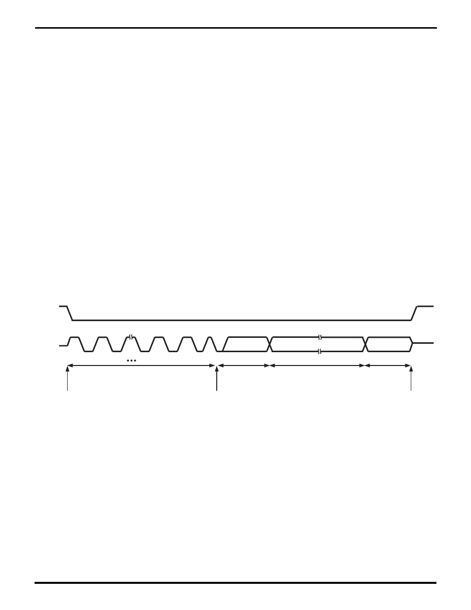
/DCD
Carrier
Detection
RxD
1
0
1
0
1
0
1
0
1
1
At least 58
Alternating Bits
16- or 48-Bit
Destination
Address
Source Address, Length,
Information
32-Bit
CRC
Start Bit
Carrier
Loss
Figure 5-7. Carrier Detection for a Received Ethernet Frame
UM009402-0201