Zilog Z16C30 User Manual
Page 73
5-6
Z16C30 USC
®
U
SER
'
S
M
ANUAL
UM97USC0100
Z
ILOG
5.5 THE MODE REGISTERS (CMR, TMR AND RMR)
(Continued)
Later sections describe each of these modes and proto-
cols individually, including the significance of the Tx and
RxSubMode bits (CMR15-12 and CMR7-4 respectively) in
each case. The various major modes use the SubMode
bits differently, to control protocol variations and options
that are specific to each mode. (Sometimes the same
SubMode option applies to two or more related major
modes.)
The TxMode field should be changed only while the
Transmitter is disabled in the TMR, as described in the next
section. Similarly, the RxMode field should be changed
14
13
12
11
10
9
8
7
6
5
4
3
2
1
0
15
TxSubMode
TxRMode
RxSubMode
RxMode
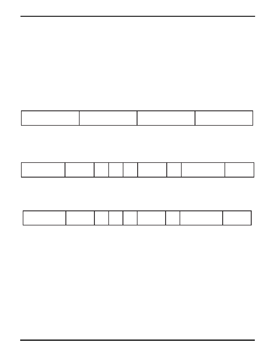
Figure 5-4. The Channel Mode Register (CMR)
TxCRCType
14
13
12
11
10
9
8
7
6
5
4
3
2
1
0
15
TxEncode
TxCRC
Enab
TxCRC
Start
TxPar
Enab
TxCRC
atEnd
TxEnable
TxParType
TxLength
Figure 5-5. The Transmit Mode Register (TMR)
RxCRCType
14
13
12
11
10
9
8
7
6
5
4
3
2
1
0
15
RxDecode
RxCRC
Enab
RxCRC
Start
RxPar
Enab
QAbort
RxEnable
RxParType
RxLength
Figure 5-6. The Receive Mode Register (RMR)
only while the Receiver is disabled in the RMR. While it’s
possible to change the TxSubMode or RxSubMode fields
while the Transmitter or Receiver is operating, the options
provided by these fields are typically static in nature and
the need to change them should seldom arise.
The Transmit and Receive Mode Registers (TMR and
RMR) contain basic control information for the Transmitter
and Receiver, including the serial format and data-integ-
rity checking. Figures 5-5 and 5-6 show the TMR and RMR
respectively.
UM009402-0201