Zilog Z16C30 User Manual
Page 28
2-2
Z16C30 USC
®
U
SER
'
S
M
ANUAL
UM97USC0100
Z
ILOG
2.2 MULTIPLEXED/NON-MULTIPLEXED OPERATION
(Continued)
68000
D15:D0
/AS
USC
AD15:AD0
/AS
VCC
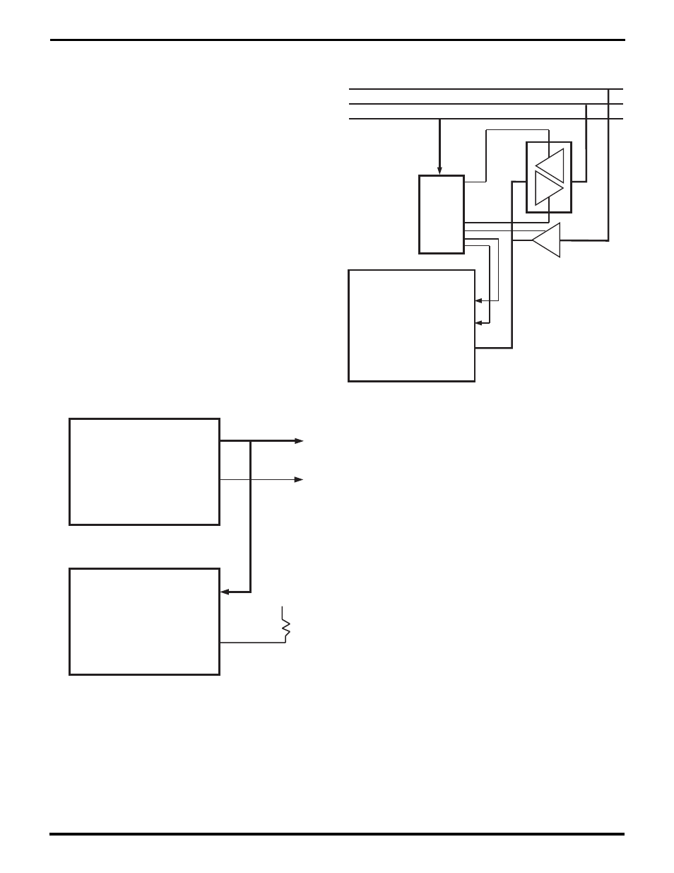
Figure 2-3. User-Friendly Interface to
Non-Multiplexed Bus
An 80x86-based system differs only in that the processor’s
ALE signal has to be inverted to produce /AS for the USC.
Figures 2-2 and 2-3 illustrate two ways to interface the USC
to a non-multiplexed host bus. Figure 2-2 includes mini-
mum hardware but requires that software write the register
address into the USC each time it is going to access a
register. In this mode the USC’s /AS pin should be pulled
up to ensure a constant high logic level. Figure 2-3 in-
cludes drivers to sequence the low-order bits of the host
address onto the USC’s AD lines, and logic to synthesize
a pulse on the /AS pin. This interfacing method has the
advantage that software can directly address the USC’s
registers.
The USC monitors the /AS pin from the time the /RESET pin
goes high until the software writes the Bus Configuration
Register. If it sees /AS go low at any point in this period,
then after the software writes the BCR, the USC captures
the state of the low-order AD lines, A//B, C//D, and /CS, at
each rising edge of /AS. If /AS remains high, software may
have to write each register address into the Channel
Command/ Address Register (CCAR) before reading or
writing a register. (If the host bus only includes 8 data lines,
AD13-AD8 can carry register addresses.)
Figure 2-2. Simple Interface to Non-Multiplexed Bus
USC
AD15-AD0
/RD, /WR
/AS
Control
Logic
Cntrl Signals
D15-D0
A15-A0
UM009402-0201