Zilog Z16C30 User Manual
Page 64
4-15
Z16C30 USC
®
U
SER
'
S
M
ANUAL
Z
ILOG
UM97USC0100
4.9 THE /CTS PIN
The
CTSMode
field of the I/O Control Register (IOCR15-
14) controls the function of this pin:
CTSMode
Function of the /CTS pin
0x
Low-active Clear to Send input
10
Low output
11
High output
When CTSMode is 00 or 01, software can handle the Clear
to Send input all by itself. Alternatively, the /CTS input can
enable and disable the Transmitter in hardware, if software
writes 11 to the TxEnable field of the Transmit Mode
Register (TMR1-0). In the latter case, the Transmitter will
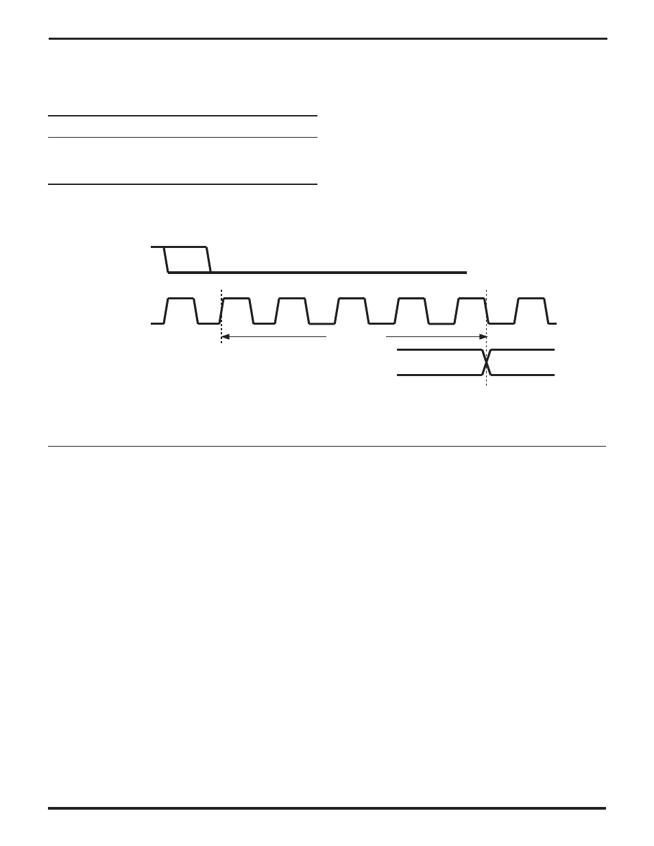
start sending a character only when /CTS is low. As shown
in Figure 4-10, if the Transmitter is otherwise “ready to go”
when /CTS goes low, the first bit active bit on TxD will begin
at the falling edge of TxCLK that is 4.5 clock periods after
the rising edge of TxCLK at which the Transmitter first
samples /CTS low.
TxCLK
(/TxC)
/CTS
TxD
1st Active Bit
4.5 Clocks
Figure 4-10. /CTS Auto-Enable Timing
If /CTS goes high during a transmitted character in an
asynchronous mode, the Transmitter finishes sending the
character before going inactive. In the same situation in a
synchronous mode, the Transmitter terminates transmis-
sion immediately.
The /CTS pin can alternatively be used as a general-
purpose output. To do this, simply program CTSMode to
10 to make the channel drive /CTS low, and to 11 to make
it drive the pin high. For such applications the designer
may want to connect a pull-up or pulldown resistor to the
/CTS pin, because the channel won’t drive the pin from the
time /RESET goes low until the software programs CTSMode
to 10 or 11.
Software can program a channel to interrupt the host
processor on either or both edges on /CTS, as described
in the earlier section "Edge Detection and Interrupts".
Typically such interrupts would be used when /CTS is an
input, that is, when CTSMode is 00 or 01. Software should
write a 1 to the
CTSDn IA
bit in the Status Interrupt Control
Register (SICR5) to make a channel detect falling edges
on /CTS, and write a 1 to
CTSUp IA
(SICR4) to make it
detect rising edges.
As described in Edge Detection and Interrupts, the
CTSL/U
bit (MISR5) is 1 if the channel has detected an
enabled edge, until software writes a 1 to the bit to clear it.
The
/CTS
bit (MISR4) reflects the state of the /CTS pin
transparently while CTSL/U is 0, but is frozen while
CTSL/U is 1. MISR4=0 indicates a high on the pin, and 1
indicates a low.
UM009402-0201