Figure 4-73, 4 - removal and re-installation – MagTek EC2000 99875607 User Manual
Page 96
4 - Removal and Re-installation
ExpressCard 2000| Instant Issuance Card Personalization System | Hardware Service Manual
Page 96
Figure 4-73 - Safe Removal Position for Embosser Cable (TOP VIEW FROM LEFT)
9) In each of the following steps, rotate the embosser daisy wheel so only empty tines are near the Allen
wrench. This saves time if the wrench slips and breaks a tine; if the broken tine were not empty, you
would have to re-install the font to another tine and re-map it in the software.
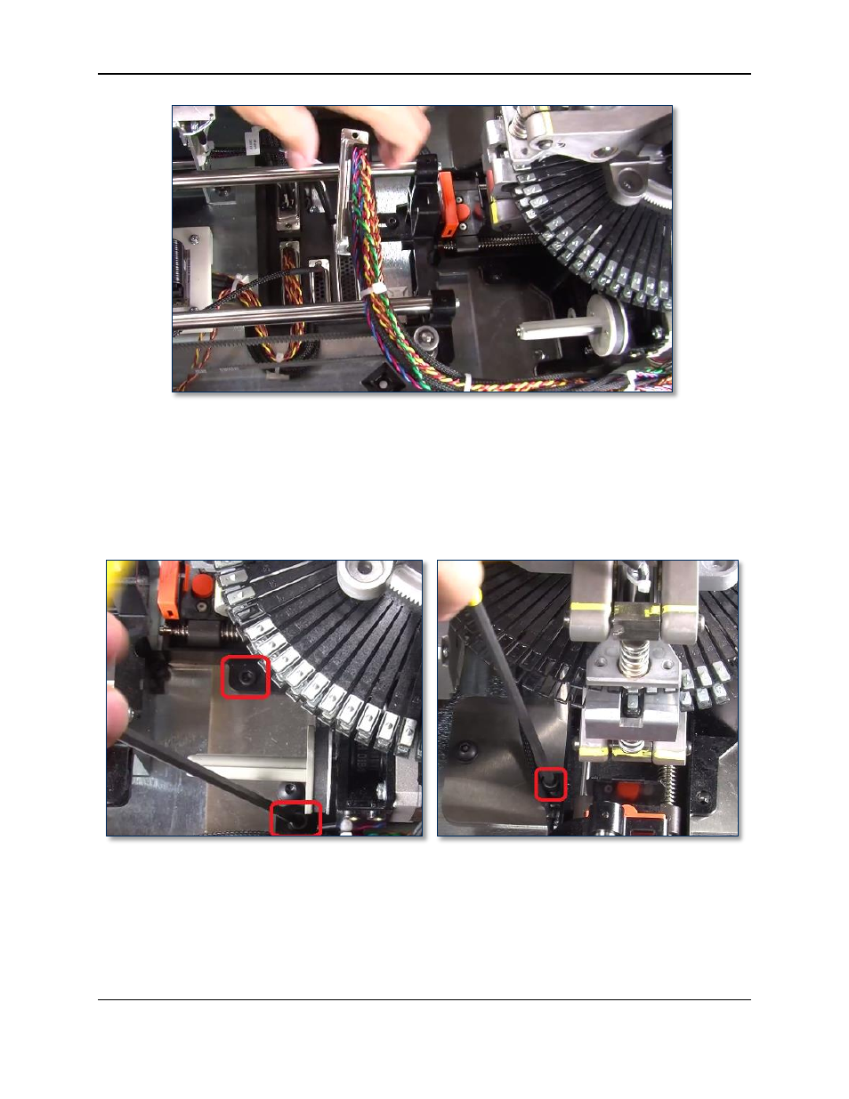
10) Use the 5/32” ball-end Allen wrench to remove the three screws that attach the rear indent module to
the embosser. The left image in Figure 4-74 shows two screws as seen from the left side of the
device, and the right image shows the final screw as seen from the rear of the device.
Figure 4-74 - Unfastening Rear Indent Module (TOP VIEW FROM LEFT and TOP VIEW FROM REAR)
11) Use the 5/32” ball-end Allen wrench to remove the four screws and washers that attach the embosser
to the top deck plate, and set them aside. The left image in Figure 4-75 shows two screws as seen
from the front of the device, and the right image shows the other two as seen from the rear of the
device.