4 - removal and re-installation – MagTek EC2000 99875607 User Manual
Page 61
4 - Removal and Re-installation
ExpressCard 2000| Instant Issuance Card Personalization System | Hardware Service Manual
Page 61
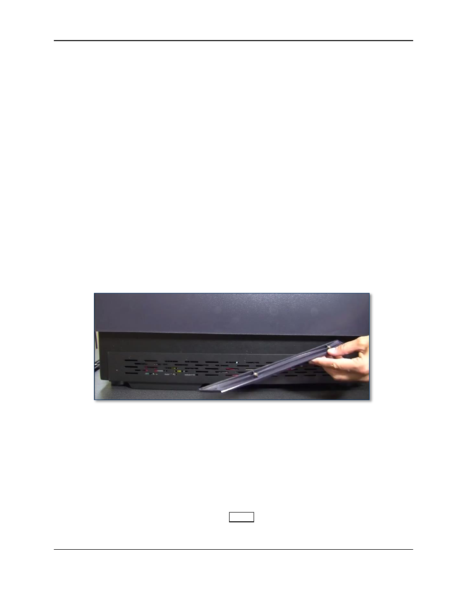
13) Use your fingers to insert the two screws that fasten the cover to the front of the device (see Figure
4-22), then use the No. 1 Philips screwdriver to loosely screw them into place to constrain the cover
from moving left to right.
14) Loosely screw in the two screws that fasten the cover to the rear plate (see Figure 4-18 and Figure
4-19) to constrain the cover from moving front to rear.
15) Fully insert the eight screws that fasten the cover to the base. Follow these helpful hints:
a) Put a light below the screw holes before attempting to line them up.
b) Use your free hand to push the cover into the right position to insert the screws.
c) It may be helpful to use the magnetic retriever tool to insert them into the holes, then use the
screwdriver or a finger to push them all the way in.
16) One by one, line up each of the plastic fastener plates below their matching screws, hold them in
place, and tighten the screws. The diagonal portion of each fastener plate will be in the midline of the
device as shown. Follow these helpful hints:
a) The easiest tool to tighten the front corner screws is a screwdriver with a heavy-duty flex
extension. If one is not available, they may be easier to tighten using the No. 1 screwdriver
leaned flush against the inside corner of the cover’s top opening.
b) For each plate, fasten the midline screw first, then the corner screw.
c) Look into the cover from above to put the screwdriver firmly into the screw head first, then
crouch next to the device to line up the plate, then tighten the screw partway.
d) Do not push the plates too hard toward the ceiling, or you may pop the screw out of its hole.
e) Screw both screws partway into the plate before tightening them all the way.
Figure 4-29 - Front Left Fastener Plate (LEFT VIEW)
17) Tighten the remaining loose screws EXCEPT the top rear right (you will tighten that after re-
installing the top access door).
18) Re-install the top access door by following the steps in section 4.2 How to Remove / Re-install the
19) Complete any other service that requires the device to be powered off and open.
20) Power up the device and test it, paying special attention to the following:
a) Test the touchscreen and manual feed slot light and functionality by creating a sample card from
the manual feed slot using the touchscreen.
b) Make sure the device shows Offline on the
Status
page when the top access door is open.
c) Test the electronic latches by testing the remote unlock function.