4 - removal and re-installation – MagTek EC2000 99875607 User Manual
Page 109
4 - Removal and Re-installation
ExpressCard 2000| Instant Issuance Card Personalization System | Hardware Service Manual
Page 109
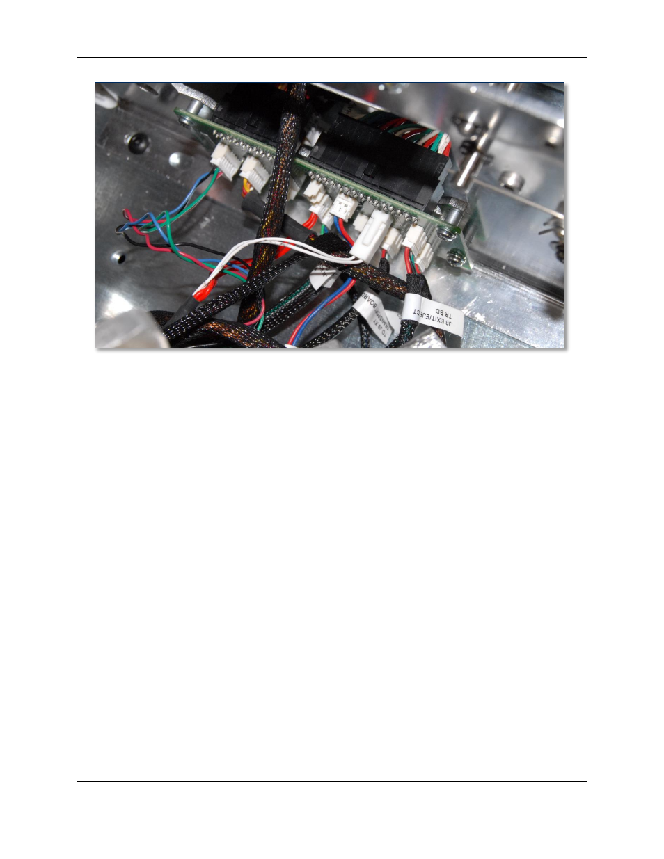
Figure 4-88 – Breakout Board Behind Tipper and Exit Ramp Module (TOP VIEW FROM FRONT)
19) Disconnect the following connectors from the breakout board behind the tipper, working from the left
side of the device to the right side. Use Figure 4-89 as a reference, and keep track of which cable
connected to which connector:
a) From connector J4 on the board, disconnect the Tipper Foil Advance Motor cable.
b) From connector J3 on the board, disconnect the Tipper Cog Grip Motor cable.
c) From connector J15 on the board, disconnect the Tipper RTD cable.
d) From connector J14 on the board, disconnect the Tipper Heater cable.
e) From connector J17 on the board, disconnect the Tipper Foil Advance Hall Sensor cable.
f) From connector J12 on the board, disconnect the Exit Fan cable.
g) From connector J8 on the board, disconnect the Tipper Card Grip Sensor cable.
h) From connector J7 on the board, disconnect the Tipper Cam Home Sensor cable.
i) From connector J9 on the board, disconnect the Tipper Card Exit Sensor cable.