Jumper configuration, Umper, Onfiguration – Teledyne LeCroy TA700_800_850 User Manual User Manual
Page 262
Catalyst Enterprises Inc.
APPENDIX F
248
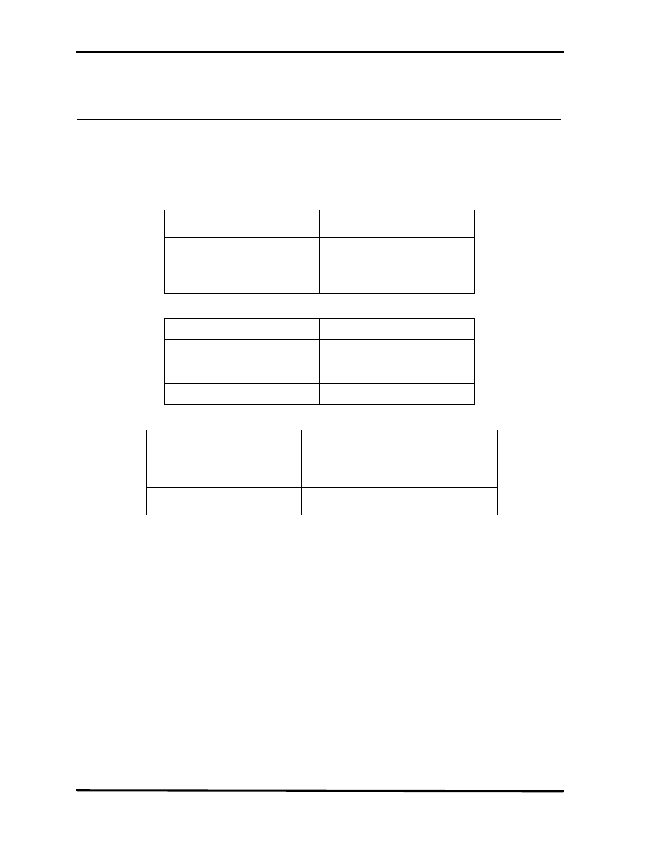
Jumper Configuration
External Power
JX1 Center +3.3V, Outer GND. JP6 must be set IAW Note 3, otherwise
a power supply contention may occur.
Trigger Out
J7 Pin 1, gnd J7 pin 2 see Figure 164.
External Outputs:
Bus Protocol & Speed Sensing
Note 1. Switch S1.2 is for internal use only.
Note 2. The TA850 operating as a PCI agent requires 256 I/O space and 4 Meg of memory
from the host system.
Note 3. With JP6 installed, power is supplied from the bus. To use external power input,
remove JP6.
JP1
1 thru 4
External Outputs [0:3]
5 thru 8
GND
JP2
Shunt 1-2 Top two
PCI-X 133MHz (Default)
Shunt 3-4 Next to top
PCI-X 66MHz
Shunt 5-6 Next to bottom
PCI
Switch S1.1
OFF
TA850 Declared as a PCI agent (Default)
ON
TA850 is transparent to the System BIOS
- 6Zi Rackmount (12 pages)
- HDO Oscilloscope Rackmount (14 pages)
- LSIB-1 Host Interfaces (44 pages)
- OC1021 Oscilloscope Cart (9 pages)
- OC1024 Oscilloscope Cart (10 pages)
- OC910 Oscilloscope Cart (2 pages)
- TTL-AUX-OUT (1 page)
- WaveJet Rackmount (1 page)
- Zi Oscilloscope Rackmount (12 pages)
- USB2-GPIB (12 pages)
- WM8Zi-2X80GS (2 pages)
- WR6ZI-8CH-SYNCH (6 pages)
- Zi Oscilloscope Synchronization ProBus Module (Zi-8CH-SYNCH) (16 pages)
- LogicStudio (42 pages)
- WaveSurfer MXs-B Getting Started Manual (126 pages)
- WaveSurfer MXs-B Quick Reference Guide (16 pages)
- X-STREAM OSCILLOSCOPES Remote Control (305 pages)
- WS-GPIB (12 pages)
- PXA125 (219 pages)
- PXD Series (42 pages)
- PXD222 (38 pages)
- Oscilloscope System Recovery (8 pages)
- LabMaster 9Zi-A (264 pages)
- LabMaster 10Zi Rackmount (8 pages)
- LabMaster 10Zi Getting Started Manual (236 pages)
- LabMaster 10Zi Operators Manual (198 pages)
- WaveAce 1000_2000 (108 pages)
- WaveAce 1000_2000 Remote Control (92 pages)
- WaveRunner Xi-A Quick Reference Guide (16 pages)
- WaveRunner XI SERIES Operator’s Manual (233 pages)
- WaveMaster Automation Command (667 pages)
- WaveMaster 8 Zi_Zi-A (190 pages)
- WaveMaster 8000A (46 pages)
- WavePro 7 Zi_Zi-A (188 pages)
- WaveExpert series Automation Manual (285 pages)
- WaveExpert 9000_NRO9000_SDA100G Getting Started Manual (50 pages)
- WaveExpert 100H Operators Manual (348 pages)
- WaveRunner Automation Command (460 pages)
- WaveRunner Xi-A Getting Started Manual (128 pages)
- WaveRunner 6 Zi and 12-Bit HRO Getting Started Manual (198 pages)
- WaveRunner 6 Zi Quick Reference Guide (20 pages)
- WaveRunner 6 Zi-ExtRef-IN_OUT (2 pages)
- WaveSurfer Automation Command (226 pages)
- HDO 4000 Getting Started Guide (48 pages)
- HDO Removable Hard Drive (2 pages)