Ta700 analyzer card, Figure 3 ta700 pci analyzer card, Status led function description (ta700) – Teledyne LeCroy TA700_800_850 User Manual User Manual
Page 17: Ta700 a, Nalyzer, Tatus, Led f, Unction, Escription, Ta700)
Introduction
Catalyst Enterprises, Inc.
3
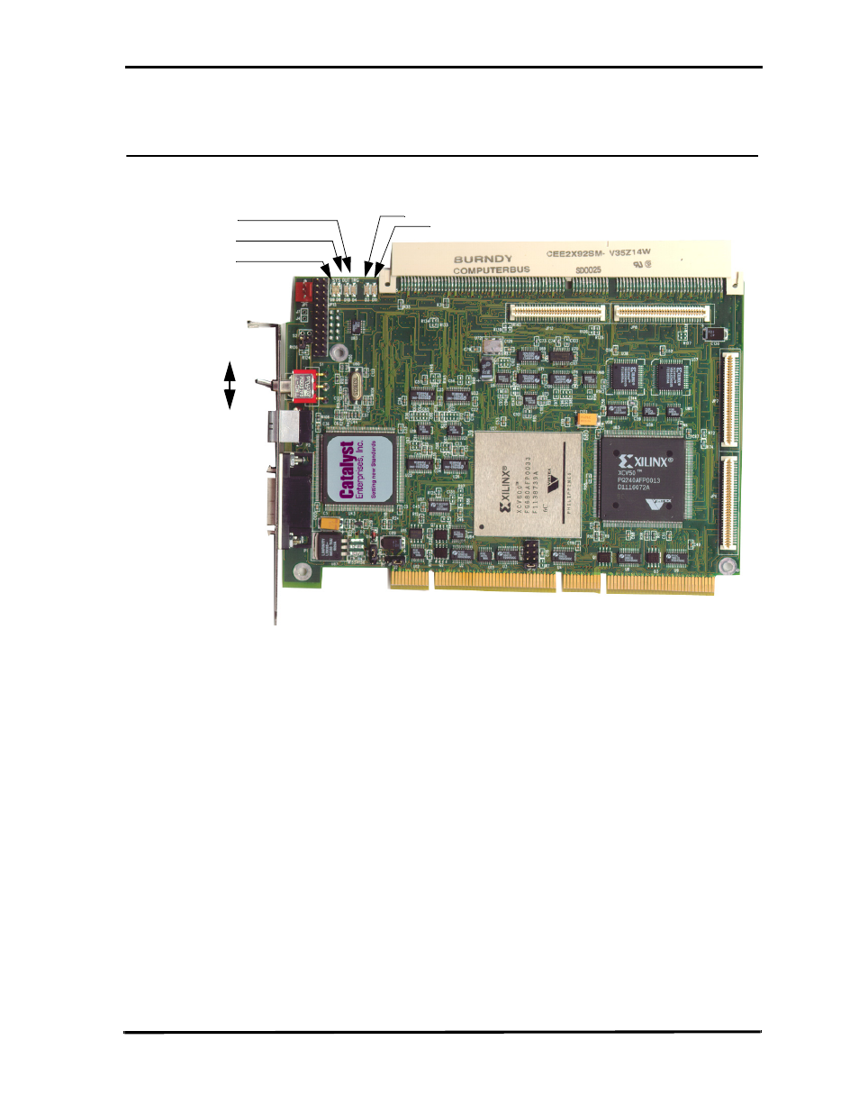
TA700 Analyzer Card
Figure 3 shows a TA700 PCI Analyzer card identifying Status LED locations, external
trigger input and output connections and the external signal input connector.
Figure 3 TA700 PCI Analyzer Card
Status LED Function Description (TA700)
For the TA700C analyzer/exerciser LED status information see APPENDIX C. For the TA700PDC
LED status information see APPENDIX D, for the TA800 LED status information see Appendix E and
for the TA850 LED status information see APPENDIX F.
SYS
When green the system and DUT voltages are within 5% of their value. If any of
+5V, +3.3V, +12V drop more than 5% the SYS LED turns red. SYS LED also
comes up red as a test on power on and then if the voltages are okay it turns
green once the software is executed. To enable voltages for sensing see page 15.
DUT
Indicates that the voltage to the DUT is on. In this case the user may not remove
or insert any card in to the top connector of the TA700
D3, D11
When illuminated, the TA700 has been configured.
TRIG
Indicates that the analyzer has met the trigger condition and is awaiting for the
defined post-trigger data to be captured.
SWITCH Function In the ON position the TA700 is transparent and connects power and PCI bus
signals to the Test Connector. In the Off position the TA700 isolates the power
and signals to the PCI bus connector and designates the TA700 to act as a PCI
Agent if jumper S2 is not installed. For jumper location see APPENDIX B.
ON
SYS
D3
D11
DUT
TRIG
OFF
SWITCH