Appendix e, Ta800 pci card, Figure 163 ta800 pci analyzer card – Teledyne LeCroy TA700_800_850 User Manual User Manual
Page 257: Status led function description, Ta800 pci c, Tatus, Led f, Unction, Escription
APPENDIX E
Catalyst Enterprises, Inc.
243
APPENDIX E
TA800 PCI Card
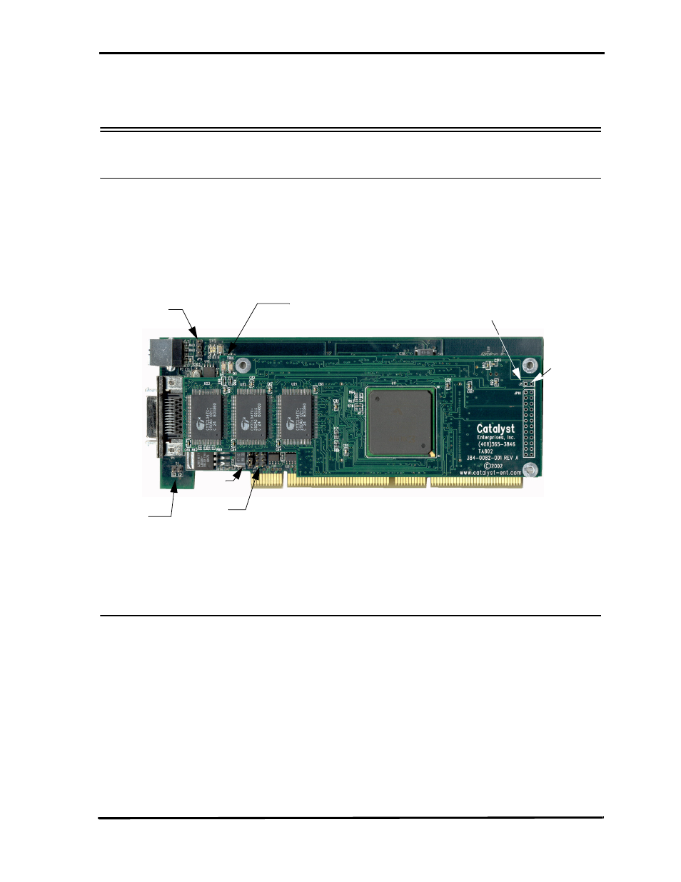
Figure 163 shows a TA800 PCI Analyzer card identifying status LED locations,
external signal, external trigger input and output connections and external power
jumper location.
Figure 163 TA800 PCI Analyzer Card
Status LED Function Description
SYS (Red/Green LED)
When green it indicates that the system voltages are within 5% of their
nominal values. If any of +5V, +3.3V +3.3V
aux
, +3.3V
io
or +12V drop by
more than 5%, the SYS LED turns red. Upon power on it comes up red
during a power self test and turns green when the software executes.
TRIG
Indicates that the analyzer has met the trigger condition and is awaiting
for the post-trigger data to be captured.
D1, D2
When both are illuminated, the TA800 FPGAs are properly configured.
S1
J7 Trigger Out
J7 GND
JP10
JP2
JP6 Pin 1
LEDs
JP7
JP1 accessible on the back of the board.
- 6Zi Rackmount (12 pages)
- HDO Oscilloscope Rackmount (14 pages)
- LSIB-1 Host Interfaces (44 pages)
- OC1021 Oscilloscope Cart (9 pages)
- OC1024 Oscilloscope Cart (10 pages)
- OC910 Oscilloscope Cart (2 pages)
- TTL-AUX-OUT (1 page)
- WaveJet Rackmount (1 page)
- Zi Oscilloscope Rackmount (12 pages)
- USB2-GPIB (12 pages)
- WM8Zi-2X80GS (2 pages)
- WR6ZI-8CH-SYNCH (6 pages)
- Zi Oscilloscope Synchronization ProBus Module (Zi-8CH-SYNCH) (16 pages)
- LogicStudio (42 pages)
- WaveSurfer MXs-B Getting Started Manual (126 pages)
- WaveSurfer MXs-B Quick Reference Guide (16 pages)
- X-STREAM OSCILLOSCOPES Remote Control (305 pages)
- WS-GPIB (12 pages)
- PXA125 (219 pages)
- PXD Series (42 pages)
- PXD222 (38 pages)
- Oscilloscope System Recovery (8 pages)
- LabMaster 9Zi-A (264 pages)
- LabMaster 10Zi Rackmount (8 pages)
- LabMaster 10Zi Getting Started Manual (236 pages)
- LabMaster 10Zi Operators Manual (198 pages)
- WaveAce 1000_2000 (108 pages)
- WaveAce 1000_2000 Remote Control (92 pages)
- WaveRunner Xi-A Quick Reference Guide (16 pages)
- WaveRunner XI SERIES Operator’s Manual (233 pages)
- WaveMaster Automation Command (667 pages)
- WaveMaster 8 Zi_Zi-A (190 pages)
- WaveMaster 8000A (46 pages)
- WavePro 7 Zi_Zi-A (188 pages)
- WaveExpert series Automation Manual (285 pages)
- WaveExpert 9000_NRO9000_SDA100G Getting Started Manual (50 pages)
- WaveExpert 100H Operators Manual (348 pages)
- WaveRunner Automation Command (460 pages)
- WaveRunner Xi-A Getting Started Manual (128 pages)
- WaveRunner 6 Zi and 12-Bit HRO Getting Started Manual (198 pages)
- WaveRunner 6 Zi Quick Reference Guide (20 pages)
- WaveRunner 6 Zi-ExtRef-IN_OUT (2 pages)
- WaveSurfer Automation Command (226 pages)
- HDO 4000 Getting Started Guide (48 pages)
- HDO Removable Hard Drive (2 pages)