Jumper configuration, Umper, Onfiguration – Teledyne LeCroy TA700_800_850 User Manual User Manual
Page 240
Catalyst Enterprises Inc.
APPENDIX B
226
DUT
Indicates that voltage to the DUT is on. In this case the user may not remove or insert any
card in the top connector of the TA700.
TRIG
Indicates that the analyzer has met the trigger condition and is awaiting for the post-trigger
data to be captured.
D3, D11 When illuminated, the TA700 has been configured.
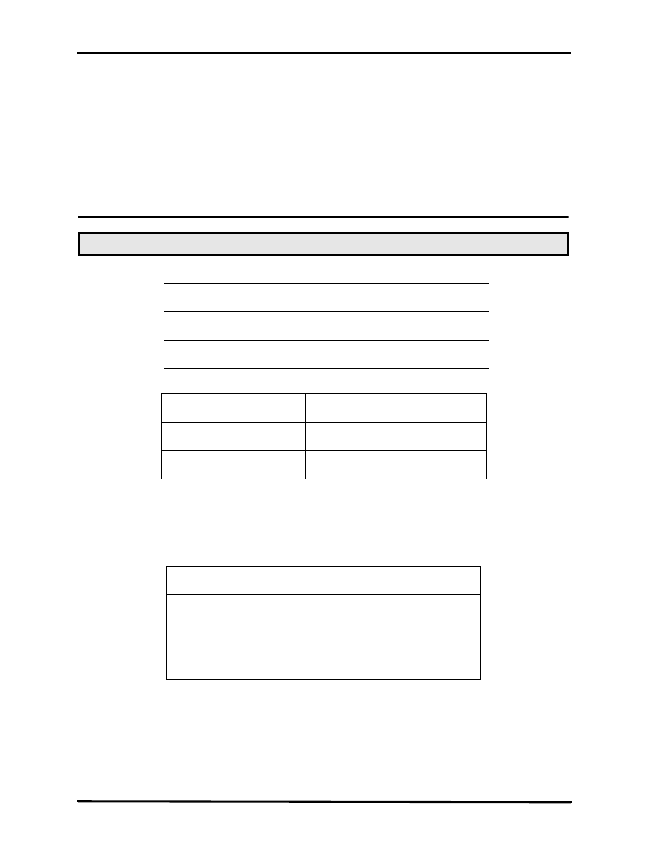
Jumper Configuration
TA700 +3.3V Power Source selection
TA700 +5V Power Source Selection
Connecting an External Power Supply
Install Shunt 1-2 center to left on JP2 (3.3V)
Install Shunt 1-2 center to bottom on JP16 (+5V)
Connect the external power supply to JP1 as follows:
This configuration applies +5V power to the TA700 from the external power supply
and redirects the 3.3V power from the on board regulator.
Note:
If your board does not have JP16 then use alternate jumper configuration as provided on page 229.
JP2
Shunt 1-2 center to left
+3.3V from on board 5V regulator
Shunt 2-3 center to right
+3.3V Bus Power (Default)
JP16
Shunt 1-2 center to bottom
+5V from external supply
Shunt 2-3 top to center
+5V Bus Power (Default)
JP1
JP1.1 Top pin
+5VEX
JP1.2 Center pin
+5VEX
JP1.3 Bottom
GND