Figure 127 signal color selection dialog, Latency report, Using the cursors – Teledyne LeCroy TA700_800_850 User Manual User Manual
Page 152: Atency, Eport, Sing, Ursors
Catalyst Enterprises, Inc.
Display Manipulation
138
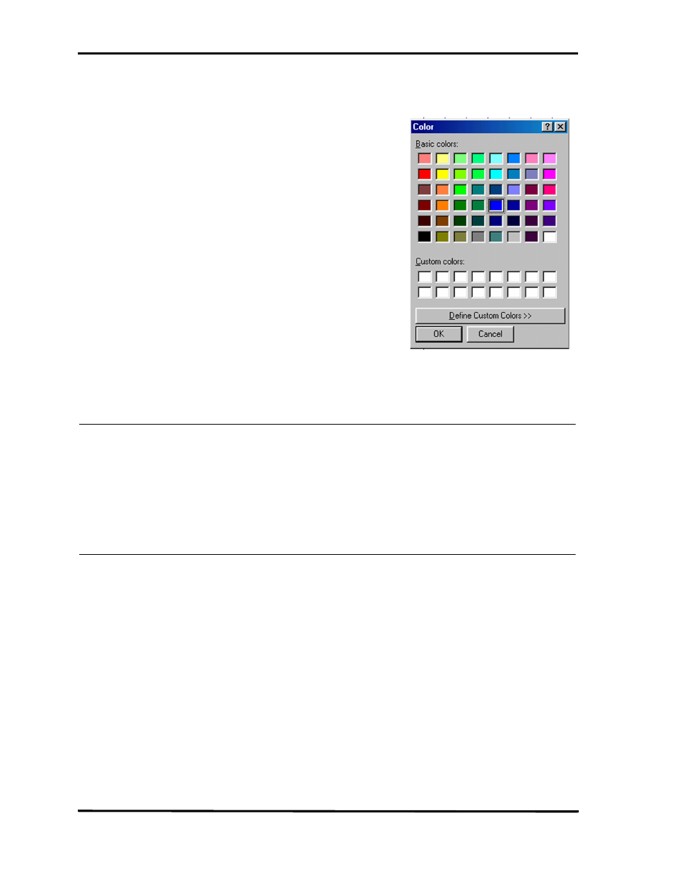
Figure 127 Signal Color Selection Dialog
Latency Report
To view Master/Target Latencies add the signals LAT_XX to the display See Figure
118.
Latency Clock vs Time
You may display latencies in clock or time units by making the choice in
the Setup Screen as shown in Figure 118.
Using the Cursors
Each of the data displays incorporates three cursors that are labeled X, Y and T. All of
them are initially overlaid and positioned at location 0, which is the trigger position of
the display. The Trigger or T cursor is always locked at location 0 of the display. It
cannot be repositioned. and serves as the measurement reference.
Moving the X Cursor
The X cursor may be dragged by selecting the left mouse button and
positioning the mouse cursor over the display cursors and then dragging
to the desired location or by clicking the left mouse button with the mouse
cursor positioned anywhere in the display. This will cause a display in the
[X-T](XRef-Trig) box to show the difference in clocks, or, if selected,
time, between the trigger and the X cursor.
Moving the Y Cursor
Similarly the Y cursor may be dragged by positioning the mouse cursor
over the cursors with the right mouse button selected or by clicking the
right mouse button with the mouse cursor anywhere in the display. This