Figure 89 timing violation results display, Figure 90 timing error signal selection – Teledyne LeCroy TA700_800_850 User Manual User Manual
Page 110
Catalyst Enterprises, Inc.
Custom Capture Data Project
96
3. Click the Event Patterns and Sequencer Tabs and create Event Patterns and a
Sequencer Program as described in Defining Event Patterns on page 62 and
Programming the Sequencer on page 64 and click Run.
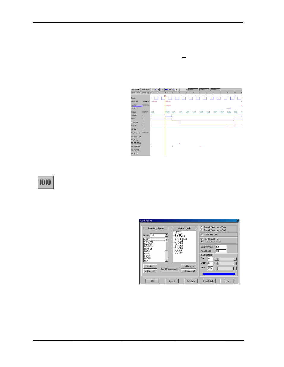
After the occurrence of a timing violation the timing violation display will open as
shown in Figure 89. The red signals represent timing violation. Bus signals are shown
as a code. As an example 00000080 indicates that the timing problem is for AD7, and
1000000C indicates the problem is for AD28, AD3 & AD2 signals.
Figure 89 Timing Violation Results Display
Display Setup
Use the setup screen to configure your display.
1. Click the Setup Screen button in the results display window to open the Timing
Error Signal selection dialog box as shown in Figure 68.
Figure 90 Timing Error Signal Selection
2. Select the signals for display from the Remaining Signals list and click Add.
3. Select other display options such as display of time in units of time or clocks,
show gridlines etc. and click OK.
To view the result as a list file output display, click the List button.