Appendix g g21 – Retrotec USACE User Manual
Page 351

Appendix G G21
With regard to data interpretation, outdoor thermography has turned
out to be more diffi cult than indoor thermography in the cold-climate coun-
tries. Indoors, the biggest technical obstacles are curtains, furniture, and
lack of space. In cold climates, IR imaging from outside buildings is limited
by the presence of ventilation gaps or robust drain planes within the exterior
envelope.
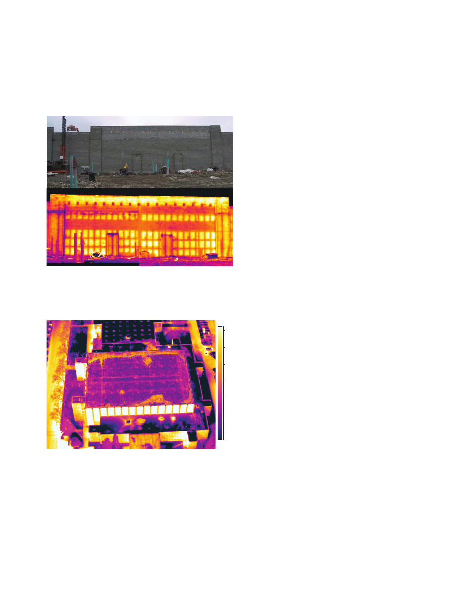
Figure G19. IR thermography of
a CMU (concrete mortar unit)
showing patterning of the grout
fi lled areas. (Image from BCRA.)
One application for outdoor IR thermography that is very useful is in the
analysis of a CMU (concrete mortal unit or cinder block wall. Due to thermal
capacity differences of the areas fi lled with grout versus the nonfi lled areas,
patterns can easily be detected (Figure G19).
11.6
18.2 °C
12
13
14
15
16
17
18
Figure G20. During the day, the
moisture trapped in the insulation
under the roofi ng cools slower
than the roofi ng, providing a
warmer pattern when observed
after sunset. (Image from BCRA.)
Thermal scanning can also be done from airborne platforms. The evalu-
ation of energy losses in communities, as well as monitoring of roof condi-
tions, has been undertaken in many countries by using thermal scanning from
fi xed-wing or rotary aircraft. Many roof evaluations can be performed during a
single fl yover, showing in great detail patterning associated with wet insulation
(Figures G20 and G21). ASTM standard C1153, “Standard Practice for Loca-
tion of Wet Insulation in Roofi ng Systems Using Infrared Imaging,” is available
for thermal roof inspections, but is outdated for today’s technology and awaits
revision.
