Retrotec USACE User Manual
Page 328

F34 ENERGY & PROCESS ASSESSMENT PROTOCOL
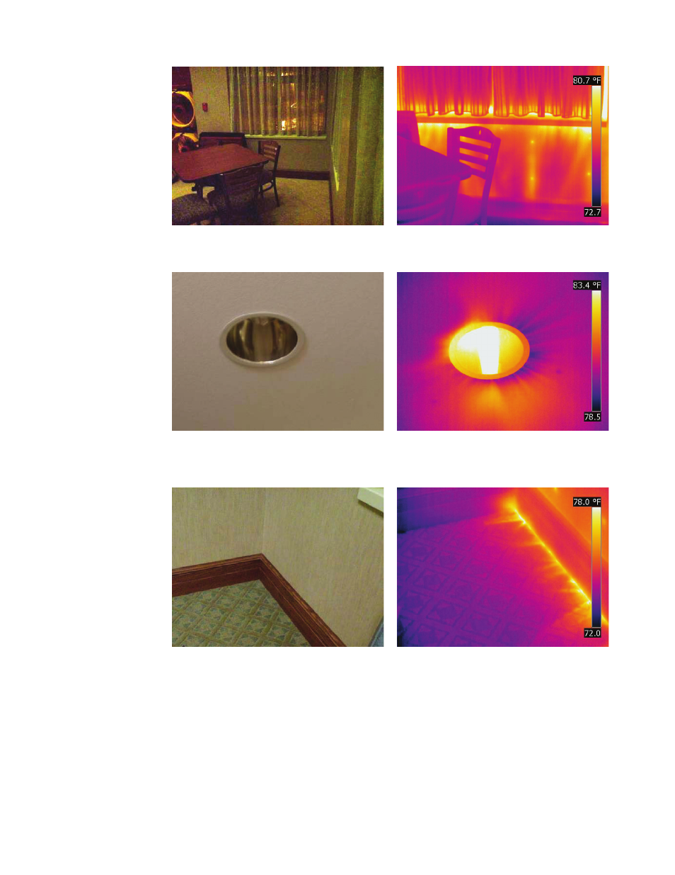
Figure F17. Window sill in a commercial facility.
Figure F18. Infrared thermogram reveals air leakage
at window sill while enclosure is depressurized.
Figure F19. Recessed light penetrating the
ceiling GWB that was intended to be the air
barrier.
Figure F20. Infrared thermogram reveals air
leakage around recessed light while enclosure
is depressurized.
Figure F21. Base trim in a commercial facility
with exterior wall on the right and interior wall
across the top/left.
Figure F22. Infrared thermogram reveals air
intrusion at base of wall while enclosure is
depressurized.
