Retrotec USACE User Manual
Page 350

G20 ENERGY & PROCESS ASSESSMENT PROTOCOL
example, in Italy and Greece, a method based on thermal scanning has been
developed for mapping the direct and indirect (chemical reactions caused by
moisture) damage caused by the moisture presence in old buildings of great
artistic value. Because restoration costs in these buildings are very high, the ex-
amination of moisture is indispensable in evaluating the building performance
and outlining the extent of possible repair. The inspection can be accomplished
by warming up the wall structure under inspection from the backside. The
measured temperature distribution depends on the moisture levels, since the
heat capacity of water is higher than that of a dry material.
The moisture damage in buildings, especially in fl at roofs, has been ana-
lyzed by applying both active and passive techniques. The roofs are scanned at
night, and the moist areas become visible as areas warmer than the surround-
ing material. This phenomenon also occurs due to a higher water heat capacity.
To locate air leaks and separate them from thermal bridges, airtightness tests
are used worldwide.
The corresponding ISO standard devoted to IR thermographic inspection
of buildings (ISO Standard 6781 Thermal Insulation—Qualitative Detection
of Thermal Irregularities in Building Envelopes—Infrared Method) unfortu-
nately, despite being the basis for some national standards, tells us nothing
about advanced data interpretation. This standard is now being revised and
updated.
When performing indoor thermal scanning, the corners and joints of
the ceiling, walls, and fl oor are always at least a little colder than their sur-
roundings. Irregular emissivity (especially in outdoor imaging), as well as
viewing angle can change the interpretation of IR thermograms, leading
to wrong conclusions. By changing a view angle of an IR camera, it is often
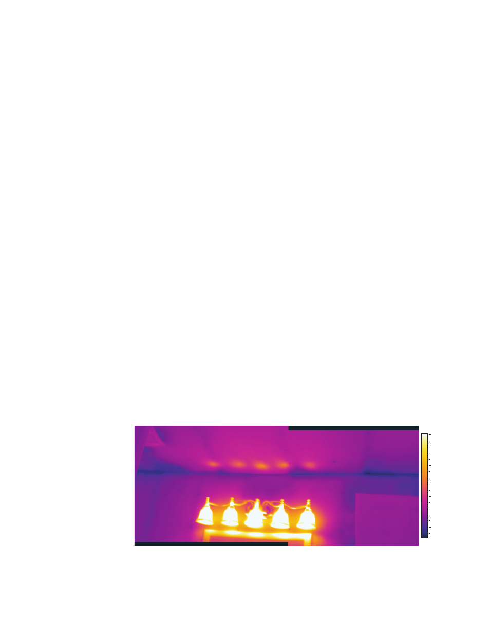
possible to eliminate the effects of refl ections. In the same way, shutting
off unwanted heat sources (light bulbs, heating radiators) or blocking cool
sources such as the sky might be required when performing IR surveys (see
Figure G18).
18.2
35.1 °C
20
25
30
35
Figure G18. Heat transfer by radiation from incandescent lighting to the ceiling above, the
adjacent wall, and the framing below. (Image from Scott Wood Associates, LLC.)
