Retrotec USACE User Manual
Page 344

G14 ENERGY & PROCESS ASSESSMENT PROTOCOL
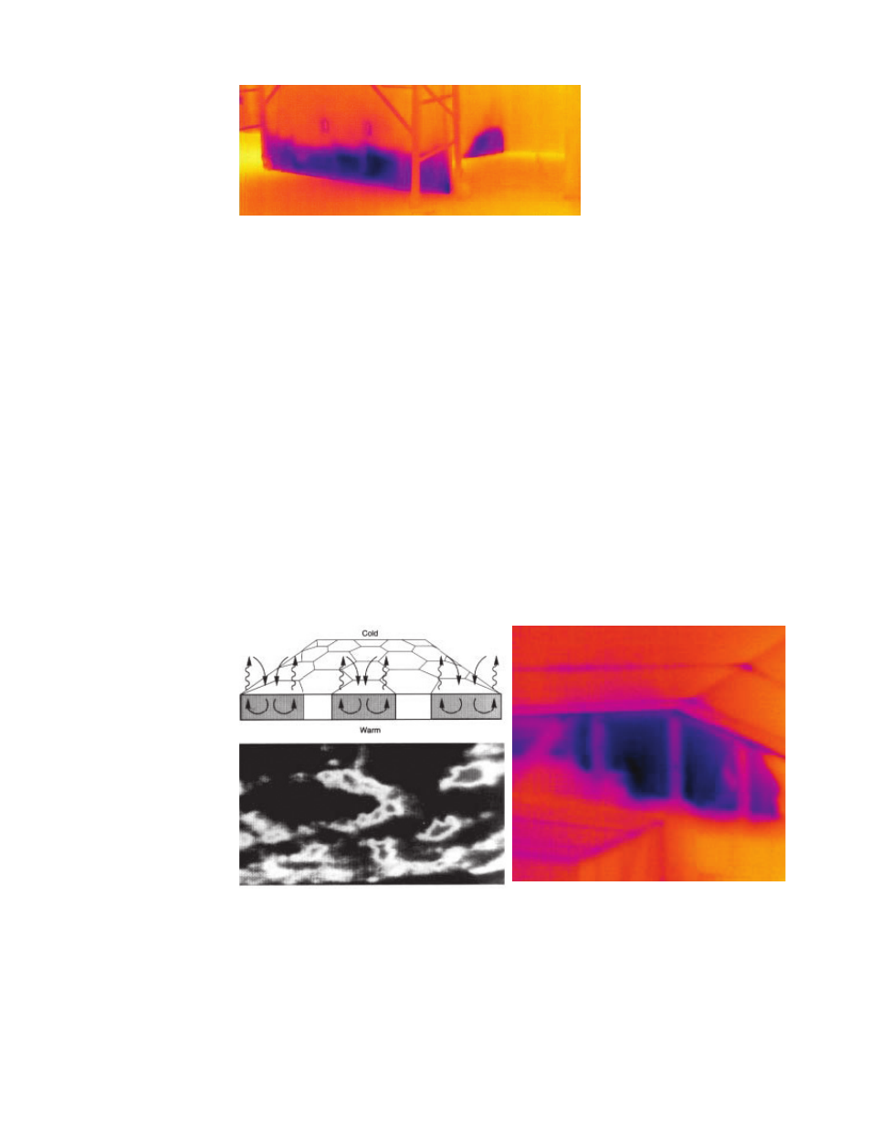
Figure G12. Evaporative cooling of
drywall that has been exposed to
moisture during fl ooding. (Image
from BCRA.)
In indoor thermal scanning, corners, joints of the ceiling, walls, and fl oor
may appear a little colder than their surroundings. Irregular surface emissivity
(especially in outdoor imaging), as well as a changing view angle, can worsen
the interpretation of the results or lead to wrong conclusions. By changing the
view angle of a scanner it is often possible to eliminate the effects of refl ec-
tions. In the same way, shutting off unwanted heat sources (light bulbs, heating
radiators) might be required when performing IR surveys.
In cold climates, with regard to data interpretation, outdoor thermography
has turned out to be more diffi cult than indoor thermography. Indoors, the
biggest technical obstacles are curtains, furniture, and lack of space. In cold cli-
mates, IR imaging from outside buildings is limited by the presence of ventila-
tion gaps or robust drain planes within the exterior envelope as well as continu-
ous thermal barriers observed in exterior insulation and fi nish systems (EIFS).
Thermal scanning and its supporting methods or methods used in parallel
(e.g., blower door tests, image processing) can be used to examine the thermal
performance of buildings and material properties. Advanced image-processing
technology can be used to compare the thermal behavior of the object under
different mechanical and temperature loads. See discussions and images in the
Whole Building Pressurization Testing section.
Figure G13. Heat transfer by convection (air
movement) within the fi berglass insulation. The
lower image is an IR thermograph showing
the heat transfer pattern. (Image from ORNL.)
Figure G14. Heat transfer by conduction in
areas of missing insulation. (Image from Joseph
Footen, Thermal Images, LLC.)
