Retrotec USACE User Manual
Page 208

D78 ENERGY & PROCESS ASSESSMENT PROTOCOL
D.4.3.2 Leaks at Gaskets, Fittings, and Valves (Waste)
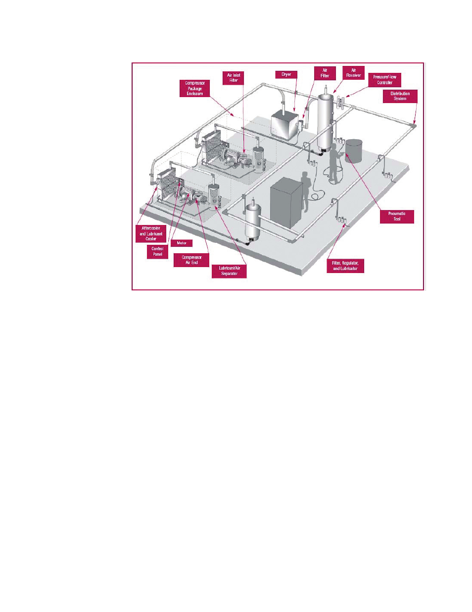
Figure D128. Typical compressed air system showing location of components and possible leak
locations.
Compressed air systems that are poorly maintained may have leaks of 20–30%
of the compressed air output (Figure D128). If a good leak detection and
repair program is implemented, this value can be reduced to lower than 10%.
Such a high rate of leaks requires unnecessary equipment to operate and
can cause system pressure drops that can affect the performance of process
equipment adjacent to the leak. A leak through an opening having an effec-
tive diameter of 3 mm (1/8 in) can result in an operating cost loss of more
than $1,000 over a year, assuming constant operation and electricity at $0.10
per kWh. Common leak locations are at couplings, fi ttings, hoses, pipe joints,
disconnect valves, and pressure regulators (Figure D129). It is best to look
for leaks when the production equipment is not operating—on a weekend, or
in the middle of the night. The use of an ultrasonic detector will aid greatly
in fi nding these leaks.
