Retrotec USACE User Manual
Page 152

D22 ENERGY & PROCESS ASSESSMENT PROTOCOL
diverse operations, the maximum required air fl ow rate does not typically
exceed 50%, and the typical air fl ow requirement is even lower. A central
exhaust system designed for a constant maximum capacity may be signifi -
cantly oversized and may consequently waste energy required to move and
clean the exhaust air. The makeup air sized for such exhaust systems may
also use excessive energy to heat and cool supplied air.
If the contaminant being removed is a particulate with some associate
weight then the rate of the exhaust air in the exhaust ducts is important. The
velocity of this air must be fast enough to keep the captured particulate moving
toward the air cleaning device. If the air fl ow is reduced, then the air velocity
will slow down and heavy contaminant type particulate will drop out in the duct.
Such situations result in reduced air fl ow at the hoods and fi lling the ductwork
with the particulate which could cause it to fall down. Such situations would be
likely in wood shops, foundaries, shot blast metal cleaning operations, etc.
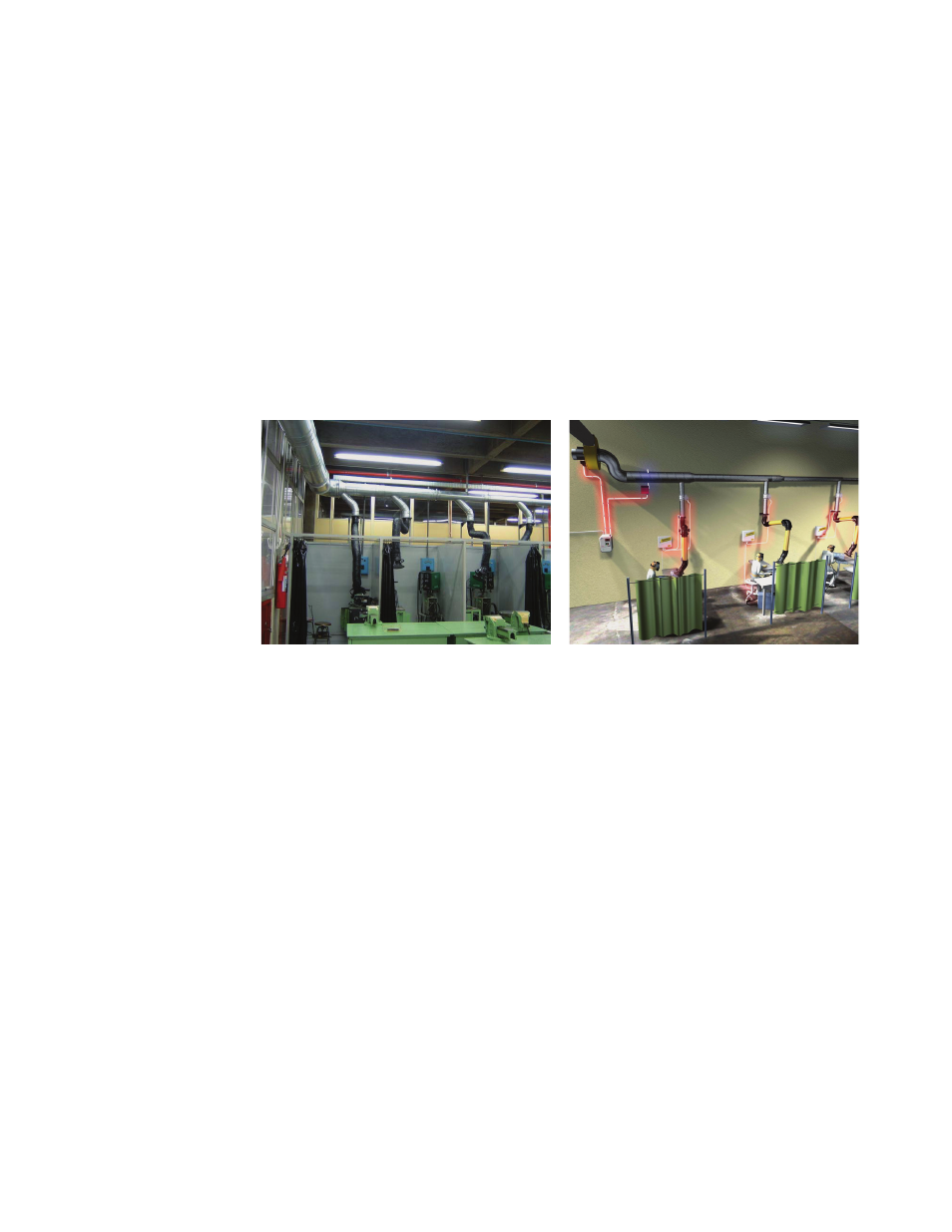
Figure D37. Example of the centralized local exhaust system for 24 workstations (left) and a
schematic of the demand variable fl ow exhaust system having a fan equipped with a VFD drive,
pressure sensor, and duct system with fl exible exhaust arms with motorized dampers (right).
Signifi cant energy reduction can be achieved by providing demand-based con-
trol of the central exhaust system. In such a system, each hood shall be equipped
with the individual damper operated from an appropriate sensor (light, mag-
netic, temperature, etc.) providing a signal to open/close the damper (Figure
D37). The exhaust air fl ow rate is controlled using a VFD and a pressure sensor
installed in a main duct. Installation of the demand-based system is economical
when there are at least three hoods and applies to processes with duty cycle
under 70%.
