Retrotec USACE User Manual
Page 327

Appendix F F33
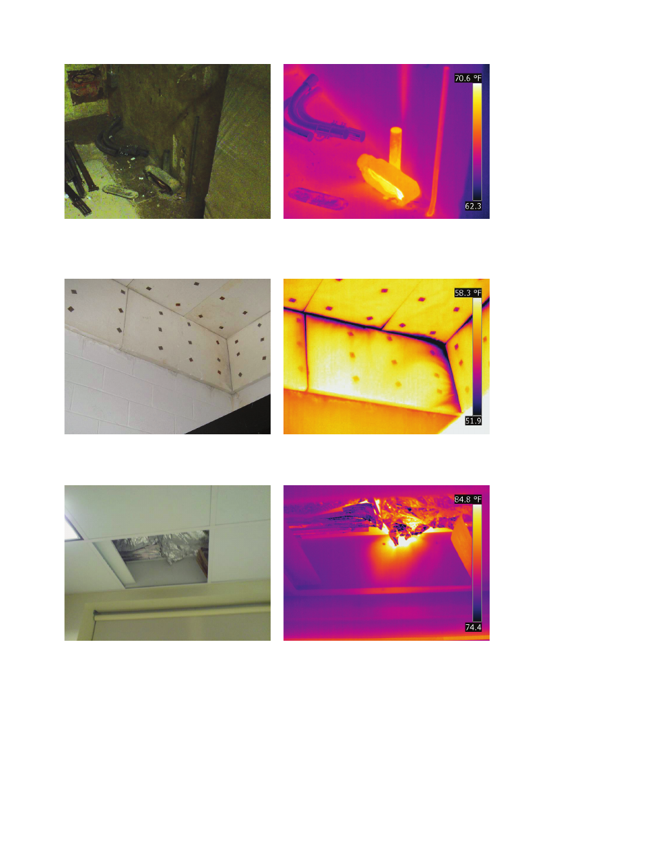
Figure F11. Derelict conduit penetration in
concrete slab.
Figure F12. Under depressurization warm air can
be seen entering into the space and presenting a
thermal anomaly on the concrete wall behind.
Figure F14. Infrared thermogram taken while
enclosure was depressurized. Air leakage in
corner most likely due to settlement cracking.
Figure F13. Insulation pinned to a below grade
CMU wall
Figure F15. Removed drop-ceiling tile reveals
foil faced insulation being used as the formal
plane of building enclosure.
Figure F16. Infrared thermogram displaying
warm air infi ltrating from attic space while
enclosure was under depressurization.
