Toa D-2000 Series User Manual
Page 159
159
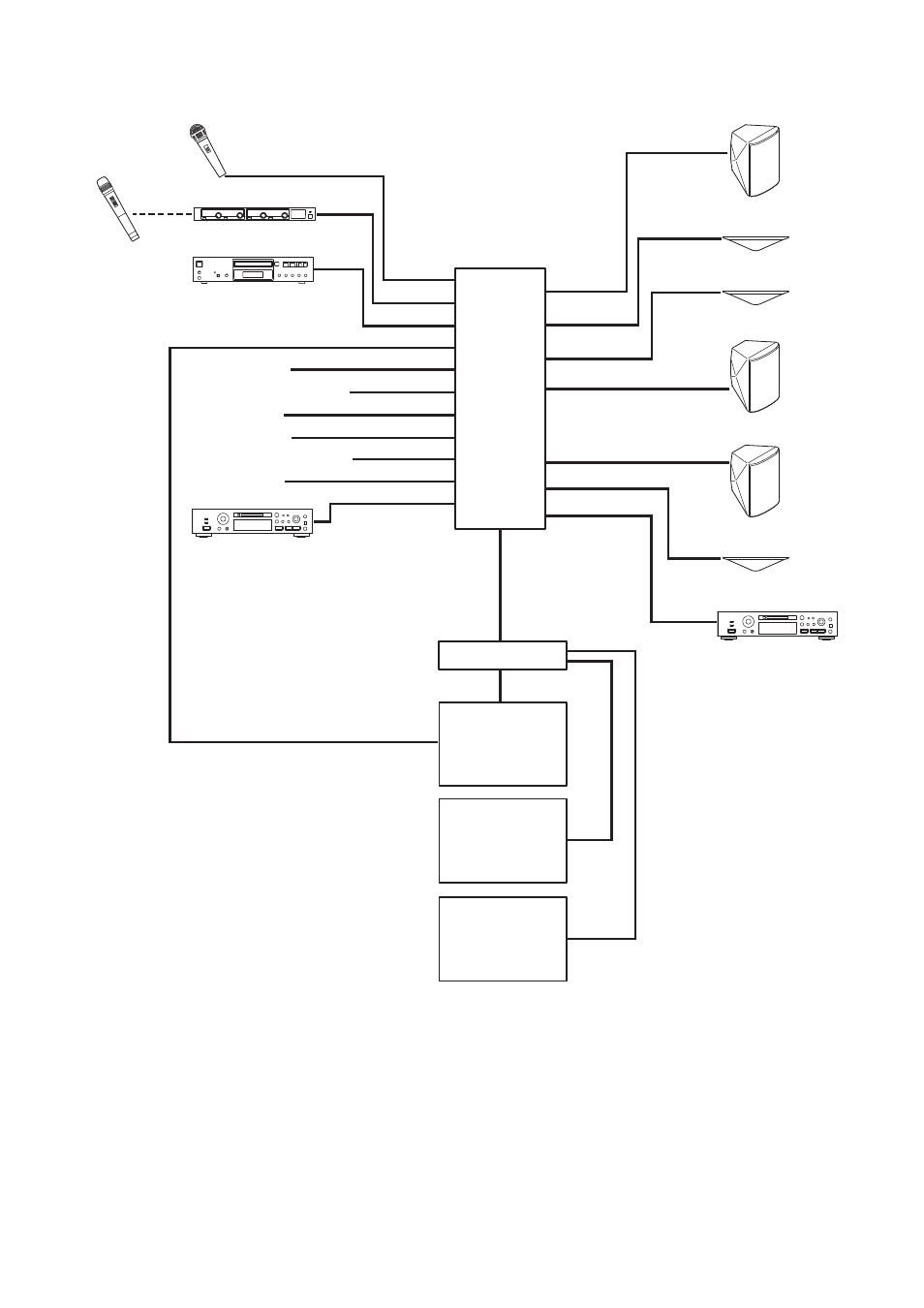
13.3.4. System diagram
A: CD player
C: MD player
A: Wireless tuner
C: MD recorder
A: Main speaker
Output 1 – 2
Input 1 – 2
Input 3 – 4
Input 5 – 6
Input 9 – 10
Input 21 – 22
MONITOR BUS
LAN
LAN
LAN
Output 3
Output 11 – 12
A: Sub-speaker
D-2008SP
A: Wireless
microphone
A: Microphone
D-2012C
(ID 1)
D-2012C
(ID 2)
D-2012C
(ID 3)
Switching hub
Input 7 – 8
Input 11 – 12
Input 13 – 14
Input 15 – 16
Input 17 – 18
Input 19 – 20
B: Microphone
B: Wireless microphone
B: CD player
C: Microphone
C: Wireless microphone
C: CD player
Output 7 – 8
Output 9 – 10
LAN
C: Main speaker
C: Sub-speaker
B: Main speaker
Output 4
Output 5 – 6
B: Sub-speaker
Note
Alphabets A, B, and C represent the equipment to be used in the banquet hall A, B, and C, respectively.