Board calibration, Test points, Board calibration test points – Rockwell Automation 7000 PowerFlex Medium Voltage AC Drive (B Frame) - ForGe Control (PanelView 550) User Manual
Page 79
Rockwell Automation Publication 7000-UM151E-EN-P - January 2013
79
Component Definition and Maintenance Chapter 3
This board also determines the health of the SCR. It has the hardware necessary
to diagnose SCR conditions and relay the status to the processor via a fail-safe
light signal along a fiber optic cable.
Board Calibration
This board requires no field calibration.
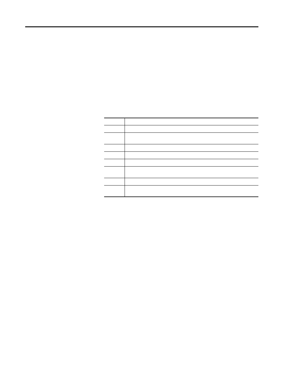
Test Points
The yellow LED (LED 1) on the SGPDB indicates that the controlled SCR has a
gating current flowing, which turns on the SCR.
TP1
SCR gate output (attach oscilloscope between TP1 and TP2 to see gating pulses)
TP2
SCR cathode output
TP3
Common reference point for all other test point measurements, except for TP1, which
uses TP2 as its reference point
TP4
The positive 20 V rail used for the SPGDB operation
TP5
The positive 5 V rail used for the SPGDB operation
TP6
The sense voltage taken from the sense resistor across the SCR being controlled
TP7
Trigger signal, which remains active for a fixed period of time after the SCR being
controlled, has turned on and the voltage across it has collapsed
TP8
Internal gating signal that indirectly turns on the SCR that is being controlled
TP9
Gating signal received from the commanding drive control board, through the
appropriate fiber optic cable