Sgct anode-to-cathode resistance – Rockwell Automation 7000 PowerFlex Medium Voltage AC Drive (B Frame) - ForGe Control (PanelView 550) User Manual
Page 269
Rockwell Automation Publication 7000-UM151E-EN-P - January 2013
269
Snubber Testing Appendix C
Table 14 - SGCT/snubber resistance values
If a device or snubber component is found to be damaged, it must be replaced
using the detailed procedures in
Component Definition and Maintenance on
.
SGCT Anode-to-Cathode Resistance
Performing an Anode-to-Cathode resistance test not only tests the integrity of
the SGCT but also the integrity of the sharing resistor. An abnormal device
resistance measurement will indicate either a shorted device or damaged sharing
resistor.
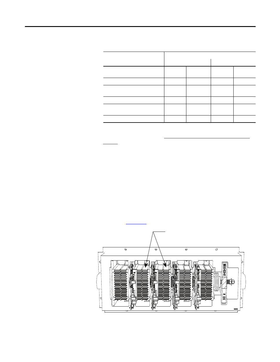
Using an ohmmeter, measure the anode-to-cathode resistance of each SGCT in
the inverter bridge, looking for similar resistance values across each device. Easy
access from the anode-to-cathode is available by going from heatsink-to-heatsink
as shown in
Figure 253
:
Figure 253 - Anode-to-Cathode resistance test points
SGCT Resistance Measurement
Measured Resistance
Inverter
Rectifier (AFE only)
SGCT Anode-Cathode Resistance
(Heatsink to Heatsink) k-Ω
(Lowest)
(Highest)
(Lowest)
(Highest)
Snubber Resistance (Test point: Heat
sink above) Ω
(Lowest)
(Highest)
(Lowest)
(Highest)
Snubber Capacitance (Test Point –
Heatsink on Right) µF
(Lowest)
(Highest)
(Lowest)
(Highest)
Measure anode-to-cathode resistance
by testing from heatsink-to-heatsink.