Flash memory transfers, Flash memory transfers on – Rockwell Automation 7000 PowerFlex Medium Voltage AC Drive (B Frame) - ForGe Control (PanelView 550) User Manual
Page 238
238
Rockwell Automation Publication 7000-UM151E-EN-P - January 2013
Chapter 5 Drive Programming and Parameters
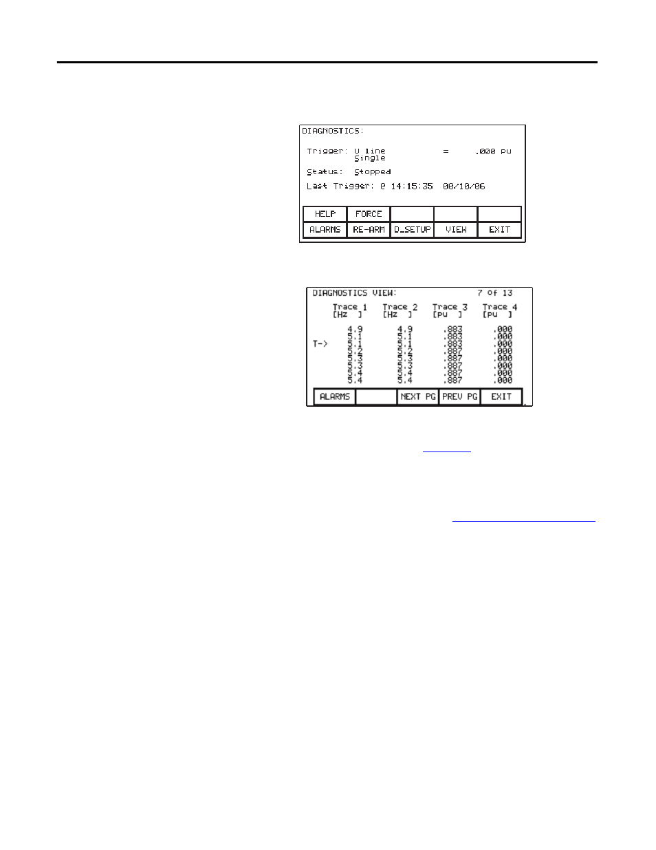
In continuous mode, the capture stops when you press [F9] to view the buffers.
Figure 228 - Diagnostic stopped
Figure 229 - View the Trend Buffer(s)
Initially, the trend view screen (similar to
) identifies the trigger point
by the “T ->”. To view data either side of the trigger point, press [F8] or [F9].
Changes made to the diagnostic list setup are not permanent until you save them
to the NVRAM. The interface will prompt you on exiting the DIAGNOSTICS
screen to save the changes to NVRAM. Refer to
for further details.
Flash Memory Transfers
The drive uses flash memory to store data in a stable format that is it is not lost
when power is disrupted. The operator interface contains flash memory in two
forms. The first is built into the operator interface, and stores the interface’s
firmware and drive parameters. You can also store this information on a
removable flash memory card.
This second form of (removable) flash enables you to physically transfer data
from one drive to another drive. All files on the flash card use a DOS format,
readable or writable by any PC containing a PCMCIA drive. PowerFlex 7000
drives support flash memory cardsharp the following INTEL memory chips:
• - 28F010
• - 28F020
• - 28F008SA
• - 28F016SA.