20b-enc-1 & 20b-enc-1-mx3 encoder interface, Input connections – Rockwell Automation 7000 PowerFlex Medium Voltage AC Drive (B Frame) - ForGe Control (PanelView 550) User Manual
Page 133
Rockwell Automation Publication 7000-UM151E-EN-P - January 2013
133
Component Definition and Maintenance Chapter 3
20B-ENC-1 & 20B-ENC-1-MX3 Encoder Interface
This encoder interface enables connecting the drive to a standard Quadrature
Encoder. The 20B-ENC encoder interface provides 3 optically isolated
differential encoder inputs for A and B phases as well as a Z track. You cannot
configure these inputs for use with a single ended encoder. The board only
supports differential encoders. The board also provides a galvanically isolated
12V/3Watt supply to power the attached encoder. You can configure the 20B-
ENC-1 Encoder interface for +5V operation, however Rockwell Automation
recommends operation at 12V.
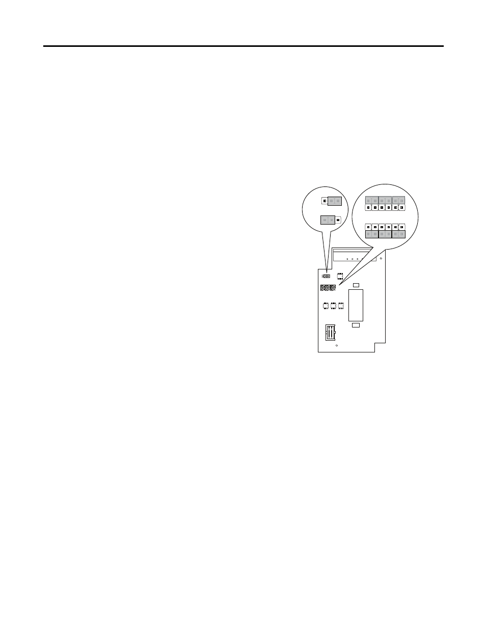
Figure 98 - Encoder Interface (20B-ENC-1 and 20B-ENC-1-MX3)
Operation at +5V does not support long cable lengths, given the need to regulate
power within 5% at the encoder. Cable resistance and capacitance makes it
difficult to regulate power at the encoder to 4.75V. Longer cables may decrease
voltage below 4.75V, causing encoder malfunction. As a general rule, using 18Avg
cabling with an Rdc of 19.3ohm/km limits the cable length to 12 m (42ft) from
the board to the encoder.
The 20B-ENC-1-MX3 encoder option is functionally identical to the 20B-
ENC-1 encoder with the addition of conformal coating.
Input Connections
All encoder interface connections occur at J1, as follows.
J1 Pin 1 A+
J1 Pin 2 A-
J1 Pin 3 B+
J1 Pin 4 B-
J3
J3
J2
+12V
1
2
3
12
11
21
+5
VR
EF
1
2
3
+5V
+12V
1
2
3
+12V
+5V
12
11
21
12
11
21
Output
Config.
J2
Intput
Config.
Note: Must be configured
for 12V operation.