Rockwell Automation 7000 PowerFlex Medium Voltage AC Drive (B Frame) - ForGe Control (PanelView 550) User Manual
Page 59
Rockwell Automation Publication 7000-UM151E-EN-P - January 2013
59
Component Definition and Maintenance Chapter 3
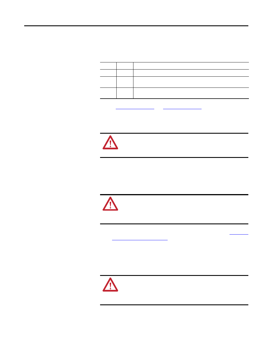
The SGCT and associated control board are a single component. Never change
the device or the circuit board individually. There are 4 LEDs on the SGCT, and
the following table describes their functions.
and
for illustrations detailing
the location of the SGCT in both standard and heatpipe models.
1. Isolate and lock out all power to the drive.
2. Note the position of the fiber optic cables for assembly.
3. To remove the SGCT, remove the gate driver power cable and fiber optic
cables. Exceeding the minimum bend radius (50 mm [2 in.]) of the fiber
optic cables may result in damage.
4. Remove the load on the clamp head assembly as described under
5. Two brackets secure the board to the heatsink. Loosen the captive screws
to free the circuit board. If necessary, adjust the position of the heatsinks to
move the SGCT freely.
6. Slide the circuit board straight out.
LED 4
Green
Solid Green indicates that the Power Supply to the Card is OK
LED 3
Green
Solid Green indicates that the Gate-Cathode resistance is OK
LED 2
Yellow
LED ON indicates the gate is ON, and Flashes alternately with LED 1 while
gating
LED 1
Red
LED ON indicates the gate is OFF, and Flashes alternately with LED 2 while
gating
ATTENTION: To prevent electrical shock, disconnect the main power
before working on the drive. Verify that all circuits are voltage-free using
a hot stick or appropriate voltage-measuring device. Failure to do so may
result in injury or death.
ATTENTION: You may damage the fiber optic cables if you strike or bend
them sharply. The minimum bend radius is 50 mm (2 inches). The
connector has a locking feature that requires pinching the tab and gently
pulling straight out. Hold the component on the printed circuit board to
prevent damage.
ATTENTION: Static charges can damage or destroy the SGCT. Properly
ground yourself before removing the replacement SGCT from the
protective anti-static bag. Using damaged circuit boards may also damage
related components. Use a grounding wrist strap for handling sensitive
circuit boards.