Configuring diagnostic trending, Diagnostic configuration – Rockwell Automation 7000 PowerFlex Medium Voltage AC Drive (B Frame) - ForGe Control (PanelView 550) User Manual
Page 156
156
Rockwell Automation Publication 7000-UM151E-EN-P - January 2013
Chapter 3 Component Definition and Maintenance
Configuring Diagnostic
Trending
The diagnostic trending is a valuable tool for troubleshooting faults in the drive.
It is a method of capturing the variation in the values of different variables over a
period of time prior to and after a fault or warning condition. In the PF7000
drive with ForGe control, the maximum number of parameters you can assign for
trending is 16. The length of the trend buffer is 100 samples.
Diagnostic Configuration
The diagnostic setup defines the source of the diagnostic trigger. This section
describes the information you must configure before using the diagnostic tool.
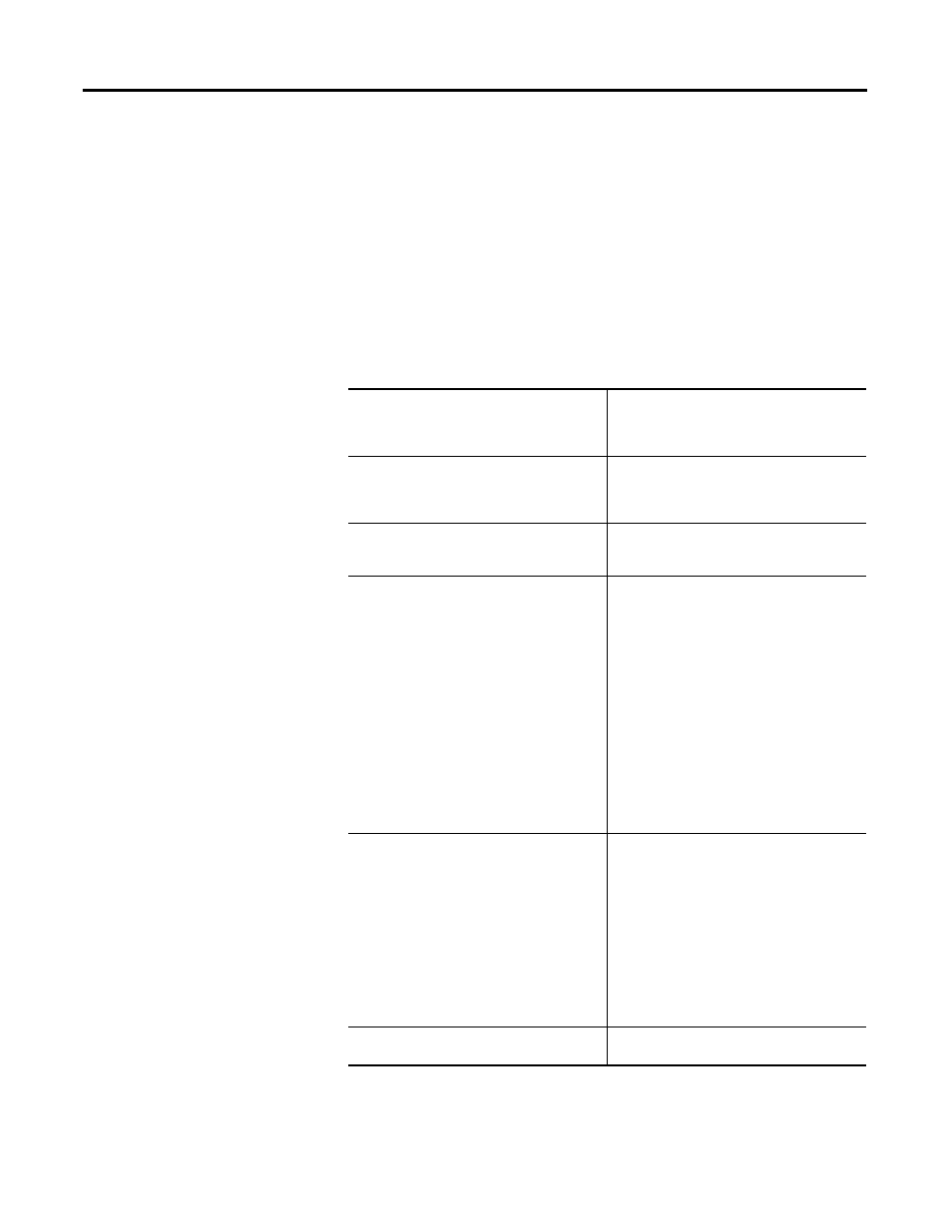
Trace
The Read-Only Parameter which is assigned to a
particular list. The item linked to Trace 1 is used
as the trigger value. There are 16 traces in total,
although not all have to be active.
Rate
The time delay between sample periods. Any
value between 0 and 20,000 msec can be set.
Use numeric keypad to enter the value and press
the enter key to accept.
Post
The percentage of the list which will occur after
the trigger point. Any value between 0 and 100%
may be used.
Trigger
Defines whether you want a continuous or a
single-shot trigger. Pressing this key will place
an S or a C in front of the trigger parameter. You
will almost always want a Single-Shot (S)
trigger.
S = Single shot >> the trigger occurs only once
and stops. The trigger must be manually re-
armed. The Re-Arm function clears the memory
buffer, which contains the data stored from the
previous trend. It is necessary to reset the
trending feature in order for a second trigger to
occur, unless you have continuous trigger
enabled.
C = Continuous capture >> auto re-arm is
enabled to collect new trends until stopped by
viewing contents of captured data.
Cond
Defines the condition that will cause the trigger.
The possible options are:
= Equal to
N= Not Equal to
> Greater than
< Less than
+ Boolean OR
N+ Boolean NOR
& Boolean AND
N& Boolean NAND
Data
Defines the trigger value with respect to the
read-only parameter in Trace 1.