Measuring resistance – Rockwell Automation 7000 PowerFlex Medium Voltage AC Drive (B Frame) - ForGe Control (PanelView 550) User Manual
Page 77
Rockwell Automation Publication 7000-UM151E-EN-P - January 2013
77
Component Definition and Maintenance Chapter 3
Measuring Resistance
The anode-cathode resistance check measures the parallel combination of the
sharing resistor and SGCT anode-cathode resistance. The sharing resistor has a
resistance much lower than that of a good SGCT, so the measurement will be
slightly less than the resistance of the sharing resistor. A measurement between 60
kΩ and 75 kΩ indicates the SGCT is in good condition and that wiring to the
SGCT is correct. If the SGCT fails, it will be in the shorted mode, 0 Ω. The
anode-to-cathode resistance check will be 0 Ω.
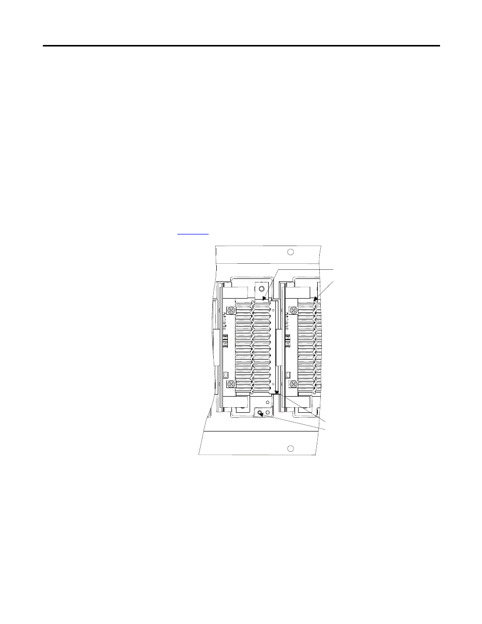
There is a test point inside the PowerCage to measure the resistance of the
snubber resistor and capacitance of the snubber capacitor. The test point is the
electrical connection between the snubber resistor and snubber capacitor. Place
one probe of the multi-meter on the test point and the other probe on the
appropriate heatsink to determine the value of the resistor or capacitor. See
Figure 57 - Resistance Measurements SGCT PowerCage
Resistance value between 2
heatsinks is sharing resistance
in parallel with anode-cathode
resistance
Resistance value between heatsink
and test point is snubber resistance