Snubber resistors – Rockwell Automation 7000 PowerFlex Medium Voltage AC Drive (B Frame) - ForGe Control (PanelView 550) User Manual
Page 68
68
Rockwell Automation Publication 7000-UM151E-EN-P - January 2013
Chapter 3 Component Definition and Maintenance
4. To detach the PowerCage itself, remove the bolts on the outer flange.
Carefully lift the PowerCage down, placing the forward face down. Do not
over-torque these bolts when replacing the PowerCage.
5. Refer to appropriate section for component replacement.
6. When replacing the PowerCage, it is important to place the bolts on the
outer flange in loosely. Torque bolts alternately on one flange and then the
opposite flange to ensure even tightening of the module. Use the suggested
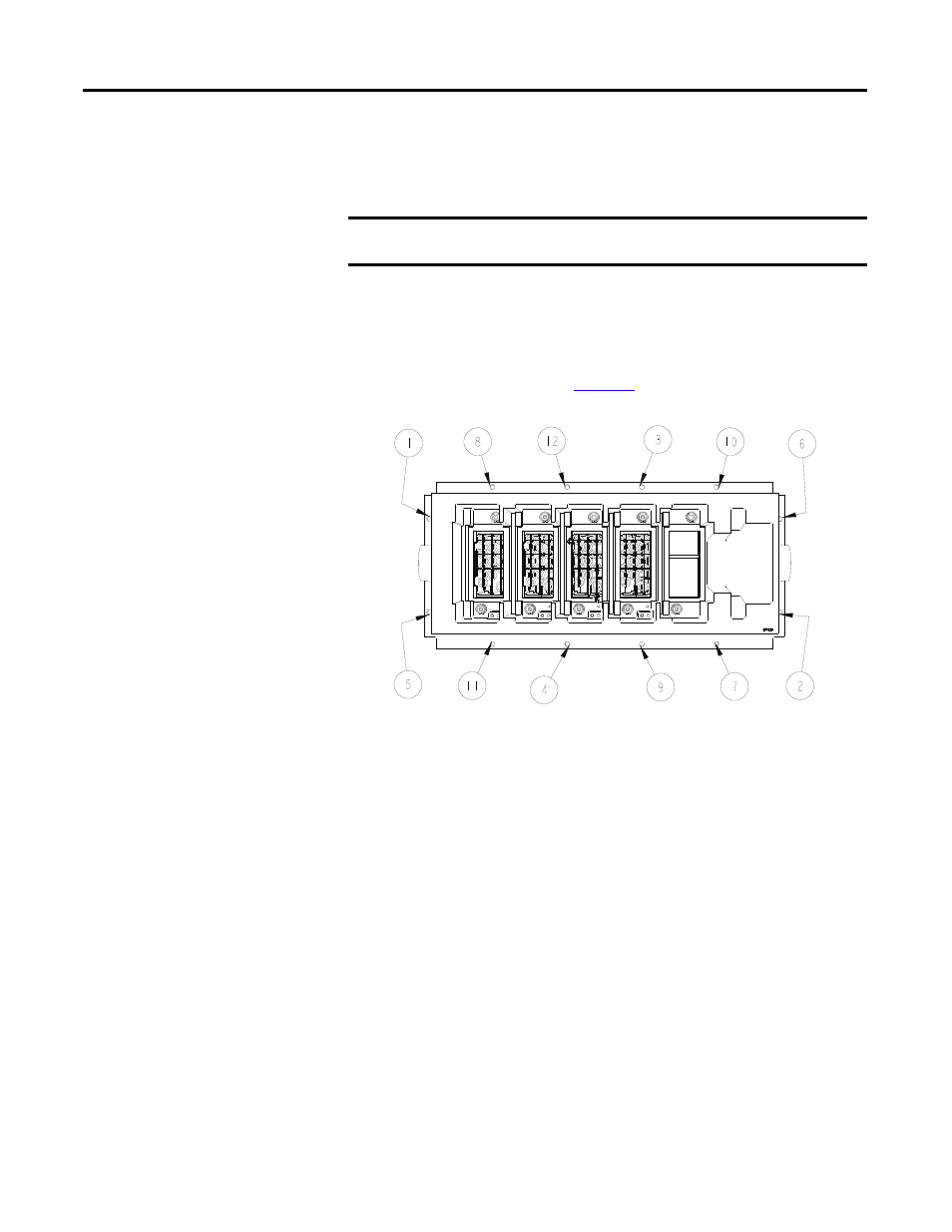
torquing sequence shown in
.
Figure 44 - Typical torque sequence
Note: The PowerCage is shown with switching components, heatsinks and
clamps removed for ease of lifting.
7. Replace interior assembly in the reverse order of removal.
Snubber Resistors
Snubber resistors connect in series with the snubber capacitors. Together they
form a simple RC snubber that connects across each thyristor (SCR or SGCT).
The snubber circuit reduces the dv/dt stress on the thyristors and reduces the
switching losses. The snubber resistors connect as sets of various wire-wound
resistors connected in parallel. The number of resistors in parallel depends on the
type of the thyristor and the configuration and frame size of the drive.
IMPORTANT The PowerCage can be heavy. Use two people to extract the PowerCage
from the drive to prevent injury or damage to the module.