Hydraulic system connection – JLG X23J - X700AJ Service Manual User Manual
Page 86
SECTION 3 - CHASSIS & TURNTABLE
3121448
– JLG Lift –
3-59
Hydraulic system connection
12. Make sure that the entire hydraulic system meets
the cleaning standard as given in level 9 according
NAS 1638 or 22/18/15 ISO/DIS 4406.
INFORMATION
CLEAN HOSES THOROUGHLY PRIOR TO CONNEC-
TION AND REMOVE ANY INTERNAL OBSTRUCTIONS.
PREVENT ANY FOREIGN PARTICLES FROM GET-
TING INTO THE HOSES BY REMOVING THE PLASTIC
C A P S O N L Y A T T H E T I M E O F T H E A S S E M B L Y.
AFTER HOSES ARE CONNECTED TO THE MOTOR,
FLOW THE HYDRAULIC CIRCUIT AND FILTER THE
OIL FROM ALL THE PARTICLES THAT MAY HAVE
CONTAMINED IT.
13. Clean the surface to be connected on the hydraulic
motor.
INFORMATION
ONLY WHEN IT IS NECESSARY TO ATTACH PIPES,
REMOVE THE PLASTIC CAPS PROTECTING THE
CONNECTIONS, THIS WILL ENSURE THAT NO FOR-
EIGN BODY GOES INSIDE THE HYDRAULIC MOTOR.
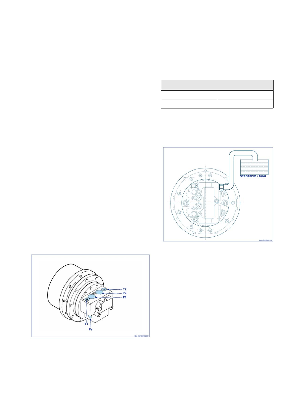
14. Pipe the hydraulic motor as shown below (for pipe
sizes and dimensions refer to the installation draw-
ing).
- Main ports: P1-P2
- Drain ports: T1-T2
- Two speed control port: Ps
Figure 3-160.
The drain pressure must be lower than the values shown
below.
Drain pipe must be directly and independently connected
to the tank. Drain port must be located on the upper side
of the motor.
Figure 3-161.
Motor drain pressure
Continuous running
Less than 1 bar
Max. intermittent
Less than 5 bar