Installation – JLG X23J - X700AJ Service Manual User Manual
Page 412
SECTION 4 - BOOM & PLATFORM
3121448
– JLG Lift –
4-13
vent it from coming out of the socket before it
engages the mounting threads.
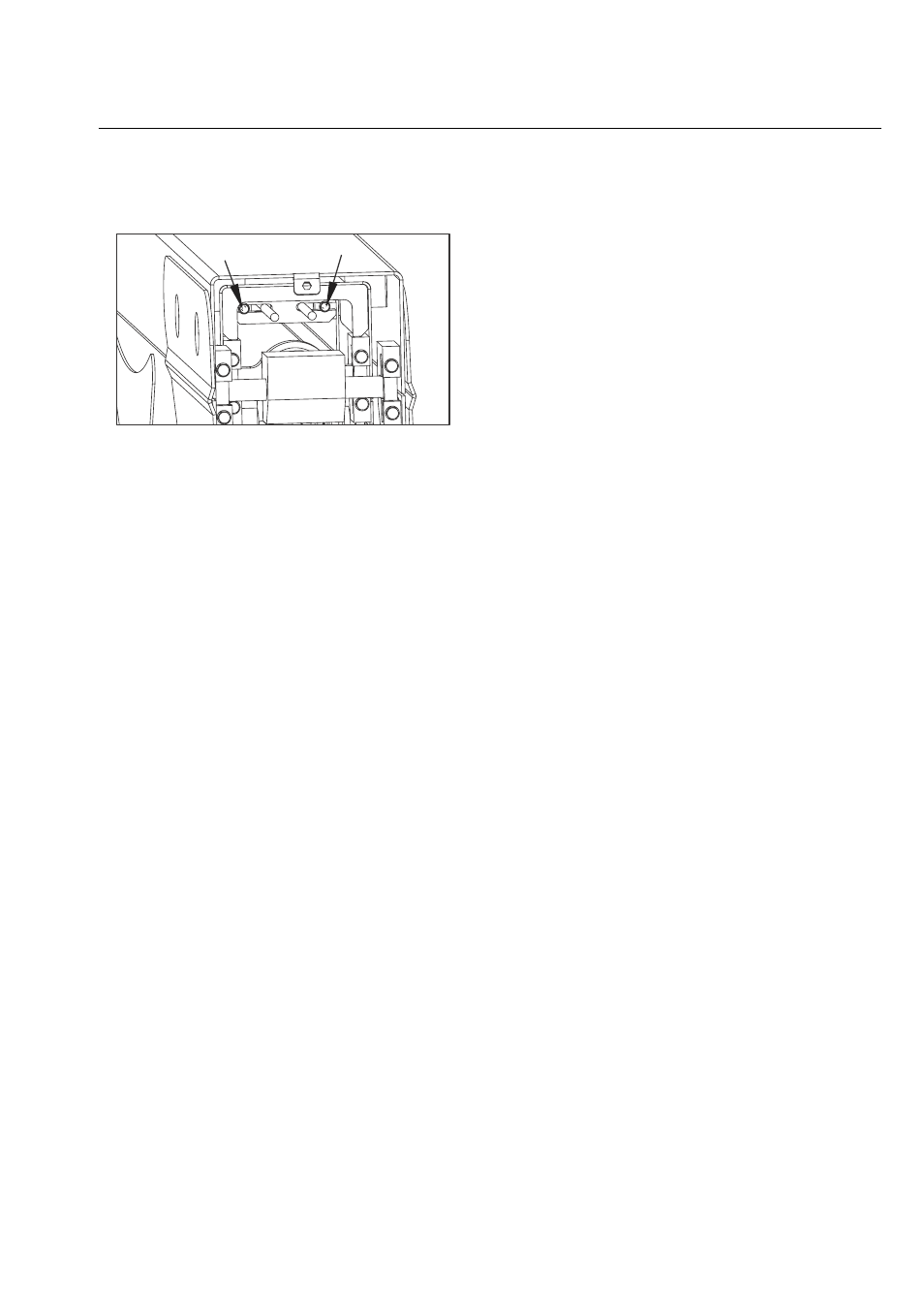
Figure 4-21.
22. Connect all the hydraulic lines to the cylinder as
tagged during the removal procedure.
23. Adjust the boom cables as outlined under Section
4.4, ROPES TENSION ADJUSTMENT PROCEDURE.
Installation
1. Using a suitable lifting device, position boom
assembly on upright so that the pivot holes in both
boom and upright are aligned.
2. Install boom pivot pin, ensuring that location of hole
in pin is aligned with attach point on upright.
3. If necessary, gently tap pin into position with soft
headed mallet. Secure pin mounting hardware.
4. Connect all wiring to the ground control box.
5. Connect all hydraulic lines running along side of
boom assembly.
6. Using all applicable safety precautions, operate lift-
ing device in order to position boom lift cylinder so
that holes in the cylinder rod end and boom struc-
ture are aligned. Insert the lift cylinder pin, ensuring
that location of hole in pin is aligned with attach
point on boom.
7. Align holes in boom structure with hole in master
cylinder. Insert the master cylinder pin, ensuring that
location of hole in pin is aligned with attach point on
boom.
8. Adjust retract and extend cables to the proper
torque. Refer to Section 4.4, ROPES TENSION
ADJUSTMENT PROCEDURE.
9. Using all applicable safety precautions, operate
machine systems and raise and extend boom fully,
noting the performance of the extension cycle.
10. Retract and lower boom, noting the performance of
the retraction cycle.