JLG X23J - X700AJ Service Manual User Manual
Page 205
SECTION 3 - CHASSIS & TURNTABLE
3-178
– JLG Lift –
3121448
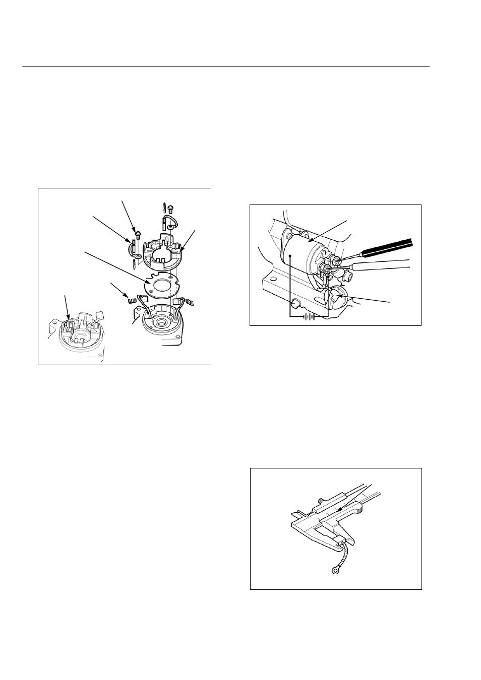
BRUSH HOLDER INSTALLATION
Note the installation direction.
Install the insulator (1), brush holder (2), negative brush
terminals (3), and two 4 x 14 mm screws (4) to the center
bracket as shown.
Install the brush springs (5) and brushes, and push the
brushes in the holders with a suitable wire (6) so that they
do not interfere with the commutator.
INSPECTION
PERFORMANCE TEST
Measure starter performance while cranking the engine.
STARTER MOTOR PERFORMANCE:
UNDER LOAD:CRANKING VOLTAGE:9.9 V
CRANKING CURRENT:103 A
ENGINE CRANKING SPEED:2,300 min-1 (rpm) min.
NO LOAD:CRANKING VOLTAGE:11.5 V
CRANKING CURRENT:31 A max.
• To get accurate results, the test must be conducted in
the normal ambient temperature.
• Battery: 55B24 (12 V 36 AH/5 HR)
• Battery cable: 15 sq. x 1.5 m (4.9 ft.) each for battery
positive cable and battery negative cable.
If the measurement is out of specification, disassemble
and inspect the starter motor.
STARTER SOLENOID
Remove the starter solenoid wire (1) from the starter sole-
noid (2).
Connect the positive (+) lead of a 12V battery to the sole-
noid terminal and the negative (-) lead to the solenoid
body. Measure the resistance between the battery and
starter motor terminals as shown.Continuity should exist
when the battery is connected and not exist when the bat-
tery is disconnected.
BRUSH LENGTH
Measure the brush length.
If the negative brush length is less than the service limit,
replace the brush and brush holder.
If the positive brush length is less than the service limit,
replace the center bracket and brush holder.
STANDARD:7.0 mm (0.28 in)
SERVICE LIMIT:3.5 mm (0.14 in)
(6)
(4)
(3)
(2)
(1)
(5)
(2)
(1)