JLG X23J - X700AJ Service Manual User Manual
Page 78
SECTION 3 - CHASSIS & TURNTABLE
3121448
– JLG Lift –
3-51
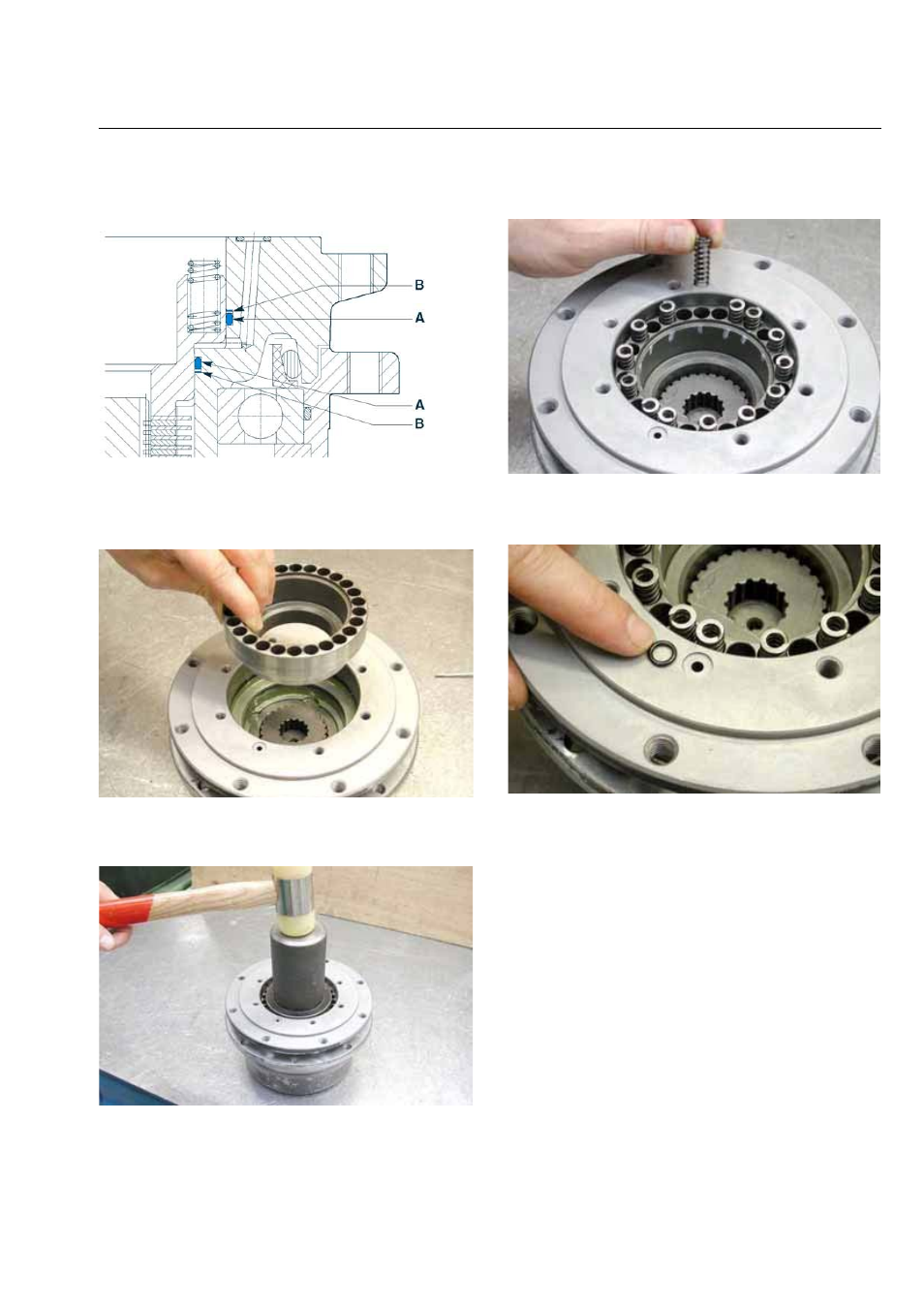
ACCORDING THE MUTUAL POSITION AS SHOWN IN
THE SCHEME.
Figure 3-145.
26. Insert the brake piston (26) inside the flanged hub
(15), being careful not to damage the seals already
fitted.
Figure 3-146.
27. By using a stopper and a rubber hammer push the
brake piston (26) against the seat shoulder (15).
Figure 3-147.
28. Insert the springs (27) into the holes of the brake pis-
ton (26) marked previously.
Figure 3-148.
29. Assemble the O-ring seal (16) in the brake port seat
on the flanged hub (15).
Figure 3-149.
INFORMATION
BEFORE MOUNTING THE HYDRAULIC MOTOR, VER-
IFY, BY USING DEPTH SLIDE GAUGE, THE CORRECT
ASSEMBLY OF THE UNIT CHECKING THE AXIAL DIS-
TANCE AS SHOWN ON THE SCHEME.
This manual is related to the following products: