Installation informations – JLG X23J - X700AJ Service Manual User Manual
Page 43
SECTION 3 - CHASSIS & TURNTABLE
3-16
– JLG Lift –
3121448
INSTALLATION INFORMATIONS
INSTALLATION PROCEDURE
Before proceeding with installation, follow the instructions
given below.
1. Properly clean the product by removing packaging
and all remains of protection padding.
2. Prepare the parts to be coupled using the installa-
tion drawing as a guide.
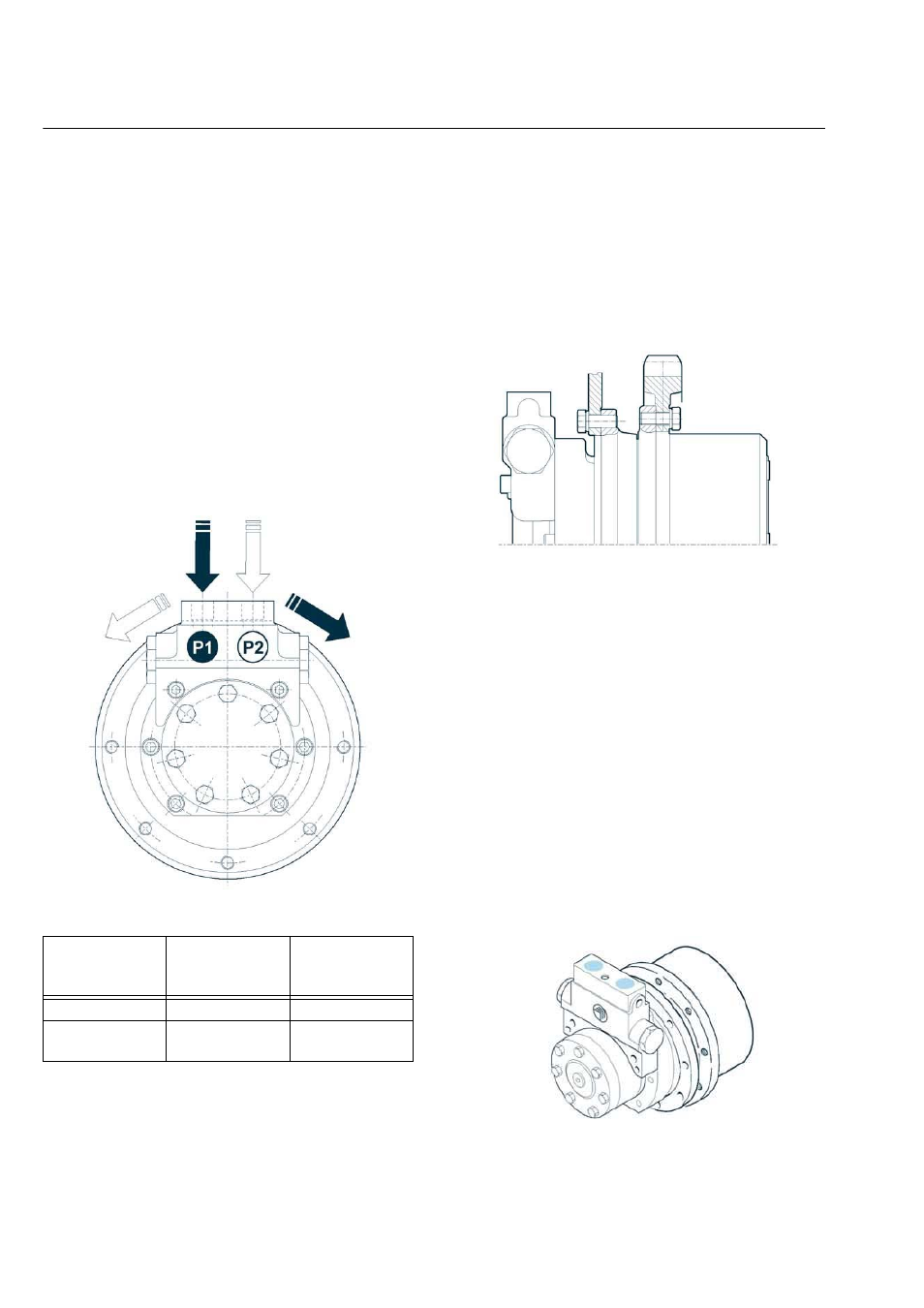
When assembling the track drive on the machine and con-
necting the hoses, follow instructions shown in below
sketch for proper direction of rotation.
Figure 3-24.
MOUNTING THE PRODUCT TO THE MACHINE
3. Move the gearmotor in the mounting area applying
lifting methods.
4. Install the motor gearbox connecting it to the
machine frame and to the sprocket using all screws
as the thread holes on to the flanges. Lock the
screws with the tightening torque shown in the fol-
lowing scheme.
Figure 3-25.
CONNECTIONS TO THE HYDRAULIC SYSTEM
5. Make sure that the entire hydraulic system meets
the cleaning standard as given in level 9 according
NAS 1638 or 18/15 ISO/DIS 4406.
6. Clean the surface to be connected on the hydraulic
motor.
INFORMATION
ONLY WHEN IT IS NECESSARY TO ATTACH PIPES,
REMOVE THE PLASTIC CAPS PROTECTING THE
CONNECTIONS, THIS WILL ENSURE THAT NO FOR-
EIGN BODY GOES INSIDE THE HYDRAULIC MOTOR.
7. Pipe the hydraulic motor as shown below (for pipe
sizes and dimensions refer to the installation draw-
ing).
Main ports: P1-P2
Figure 3-26.
Oil port inlet
Oil port outlet
Direction of
rotation (view
from motor)
P1
P2
Clockwise
P2
P1 Counterclock-
wise