JLG X23J - X700AJ Service Manual User Manual
Page 350
SECTION 3 - CHASSIS & TURNTABLE
3121448
– JLG Lift –
3-323
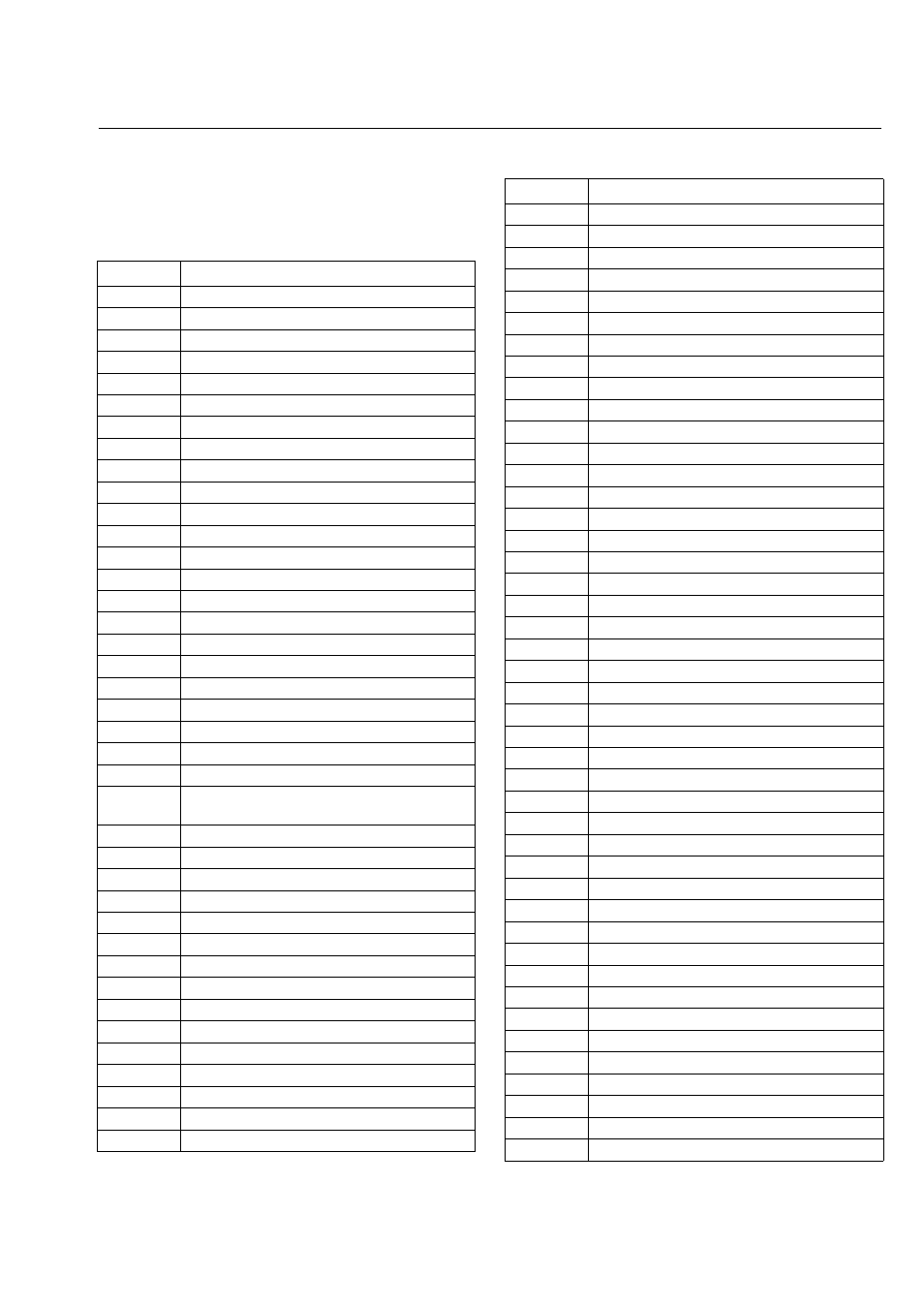
Code designations in circuit diagrams (DIN
40719)
Code
Designation of electrical component
A 1
Equipment box
A 2
Equipment panel
A 3
Automatic start-stop
A 4
Starter protection module
B 1
Temperature sensor
B 2
Speed pulse sensor
B 3
Oil pressure sensor
B 4
Horn
C1
Capacitor
E1
Heater for fuel filter
F1
Fuse
G1
Battery
G2
Generator (alternator)
G3
Flywheel generator
H 1
Indicator lamp, generator telltale
H 2
Indicator lamp, oil pressure
H 3
Indicator lamp, engine temperature
H 4
Indicator lamp, air cleaner (maintenance
switch)
H 5
Indicator lamp, broken belt
H 6
Indicator lamp, preheat monitor
H 7
Indicator lamp, fan monitor
H 8
Remote display: engine on
K 1
Control relay 1 for start / start repeat interlock
K 2
Control relay 2 for preheat
K 3
Control relay 3 für speed control
K 4
Engine protection relay
K 5
Delay relay
K 6
Start interlock relay
K 7
Timer relay (impulse relay)
K 8
Power relay
M1
Starter motor
MG
Starter-generator
N 1
Regulator for starter-generator
N 2
Regulator for flywheel generator
N 3
Regulator for alternator (unless integrated)
N 4
Pulse sensor (additional for syncro-regulator)
P 1
Operating hours counter
P 2
Revolution counter
P 3
Pressure display
R 1
Preheat glowplug
R 2
Heating flange
R 3
Line resistor for preheat system
R 4
Resistor
R 5
Line resistor with thermal time switch
S 1
Preheat starter switch (5 positions)
S 2
Master switch
S 3
Preheat starter switch (3 positions)
S 4
Start-stop switch
S 5
Speed control switch
S 6
Engine temperature switch
S 7
Oil pressure switch
S 8
Pressure switch for air cleaner
S 9
Fan monitoring switch
S 10
Preheat temperature switch
S 11
Remote start switch
S 12
Remote stop switch
T1
Engine speed measurement transmitter
V 1
Decoupling diode
V 2
Freewheeling diode
V 3
Zener diode
V 4
Suppressor diode
W 1
Earth (ground), negative return line
W 2
Screened line at generator
X 1
Terminal strip on equipment box
X 2
Flat-plug distributor
X 3
Plug at emergency stop switch
Code
Designation of electrical component